
The NTPixie, A WiFi Nixie Tube Clock

I have always thought that nixie tubes are one of the coolest inventions ever made. The novelty of having such an intricate assembly of blown glass and spot welded numbers just to simply display digits is something I've always admired.
What's a Nixie Tube?
Before the invention of the LED or the seven segment display, engineers needed a device capable of displaying digits for things like voltmeters, multimeters, and frequency counters.

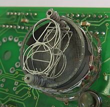
IN-18 Nixie (left), Broken GN-4 (center), GN-4 Cycling through digits (right)
To solve this problem Engineers in the USSR created nixie tubes which were made of 10 digits encased in blown glass that was sealed with Neon gas. The tubes have a wire mesh anode with multiple digits acting as the cathodes. When voltage is applied across the two the Neon gas directly around the digit glows.
Project Requirements
I've looked into simply purchasing a nixie tube clock in the past but there were always a few key wants that I had for a clock that could not be found in available models online.
The project requirements I've set for this clock are listed below.
- 6 Digits in order to display seconds
- Neon bulb colons between the hours, minutes, and seconds
- WiFi, or atomic capability to have a perfect synchronized time
I decided to use the IN-12 nixie tube due to its relatively low cost and the horizontal mounting making them ideal for the design I had in mind.

For the time accuracy I decided on using the Raspberry Pi Pico W and using the WiFi capability to sync to NTP time servers.
Design
For the design I started on the PCB side of things as that is what I was less familiar with. To drive the nixie tubes I decided on using the K155ID1 nixie tube driver. For the power supply I decided on using the NCH8200HV. Finally, for the colons I decided on using NE-2 bulbs.
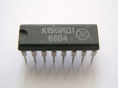
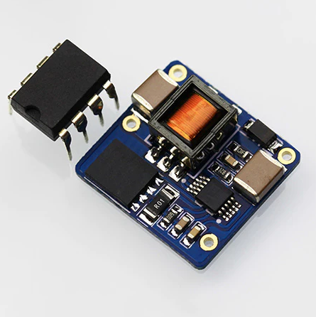
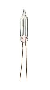
K155ID1 (left), NCH8200HV (center), NE-2 bulb (right)
After a few design revisions this is the final PCB and schematic that I came up with.


Schematic (left), PCB layout (center), 3D View (right)
To save cost on ordering the PCB I decided to design it to be snapped in half and then both pieces stacked on top of each other connected via B2B connectors.

As for the design of the case, I was originally thinking of making a wooden case but did not have a wood shop at my disposal so I decided on making a clear resin SLA enclosure to sell the retro N64 look. The final case design I came up with is below.

Firmware
For this project I decided to use MicroPython on the Pico as it has more documentation and support online for this type of project. Below is the code I wrote for the firmware running on the clock.
import network
import ntptime
from machine import Pin, Timer
from time import localtime, sleep, time

# Define the pins for each nixie tube

nixie_pins = [
    [6, 4, 5, 7],  # nixie tube 1
    [22, 20, 21, 28],  # nixie tube 2
    [2, 0, 1, 3],  # nixie tube 3
    [18, 16, 17, 19],  # nixie tube 4
    [10, 8, 9, 11],  # nixie tube 5
    [14, 12, 13, 15]  # nixie tube 6
]

colon_pin_1 = Pin(26, Pin.OUT)
colon_pin_2 = Pin(27, Pin.OUT)

# Define the lookup table for digit to binary conversion
digit_to_binary = {
    0: [0, 0, 0, 0],
    1: [0, 0, 0, 1],
    2: [0, 0, 1, 0],
    3: [0, 0, 1, 1],
    4: [0, 1, 0, 0],
    5: [0, 1, 0, 1],
    6: [0, 1, 1, 0],
    7: [0, 1, 1, 1],
    8: [1, 0, 0, 0],
    9: [1, 0, 0, 1]
}

# Connect to Wi-Fi
sta_if = network.WLAN(network.STA_IF)
sta_if.active(True)
sta_if.connect("WIFI_SSID_HERE", "WIFI_PASSCODE_HERE")
while not sta_if.isconnected():
    pass

# Set up the pins for each nixie tube
nixie_tubes = []
for pins in nixie_pins:
    nixie_tube = []
    for pin in pins:
        nixie_tube.append(Pin(pin, Pin.OUT))
    nixie_tubes.append(nixie_tube)
    #print(nixie_tubes)

# Set up a timer to update the display every second
timer = Timer(-1)

ntptime.settime()
# Define a function to update the display
def update_display(timer):
    # Get the current time from the NTP server
    print(time())
    current_time = localtime()
    # Apply the UTC offset (in seconds)
    seconds_offset = 0 #using https://time.is
    utc_offset = -5 * 60 * 60 - seconds_offset # for example, 1 hour ahead of UTC
    # -5 = CST -7 = PST
    current_time = localtime(time() + utc_offset)
    if current_time[4]==10 and current_time[5]==10:
        ntptime.settime()
        print("NTP SYNC")
    if current_time[3]>12:
        twelve_hour_time = current_time[3]-12
    else:
        twelve_hour_time = current_time[3]
    #print(current_time)
    #print(twelve_hour_time)
    # Convert the time to digits
    digits = [
        twelve_hour_time // 10,  # hour tens
        twelve_hour_time % 10,  # hour ones
        current_time[4] // 10,  # minute tens
        current_time[4] % 10,  # minute ones
        current_time[5] // 10,  # second tens
        current_time[5] % 10   # second ones
    ]

# Code below is to cycle less common digits to in order to prevent leaking this section should be reworked some day

    if current_time[3]==3 and current_time[4]==0:
        digits = [0,0,0,0,0,0]
    elif current_time[3]==3 and current_time[4]==1:
        digits = [1,1,1,1,1,1]
    elif current_time[3]==3 and current_time[4]==2:
        digits = [2,2,2,2,2,2]
    elif current_time[3]==3 and current_time[4]==3:
        digits = [3,3,3,3,3,3]
    elif current_time[3]==3 and current_time[4]==4:
        digits = [4,4,4,4,4,4]
    elif current_time[3]==3 and current_time[4]==5:
        digits = [5,5,5,5,5,5]
    elif current_time[3]==3 and current_time[4]==6:
        digits = [6,6,6,6,6,6]
    elif current_time[3]==3 and current_time[4]==7:
        digits = [7,7,7,7,7,7]
    elif current_time[3]==3 and current_time[4]==8:
        digits = [8,8,8,8,8,8]
    elif current_time[3]==3 and current_time[4]==9:
        digits = [9,9,9,9,9,9]

    print(digits)
    # Convert the digits to binary and display them on the nixie tubes
    for i in range(6):
        binary = digit_to_binary[digits[i]]
        for j in range(4):
            nixie_tubes[i][j].value(binary[j])
    colon_pin_1.value(1)
    colon_pin_2.value(1)
    sleep(0.5)
    colon_pin_1.value(0)
    colon_pin_2.value(0)

# Start the timer
timer.init(period=1000, mode=Timer.PERIODIC, callback=update_display)

# Put the device to sleep to save power
while True:
    sleep(1)  # can be interrupted by timer events
Input WiFi SSID, password, and timezone for this code to run
Final Assembly
Below are renders and pictures of the final design up and running.


You can see an orbital view of the design by dragging on the model below.


Finished photos of the clock
Conclusions
I have been using it on my bedside for the past few weeks now and it has kept time perfectly and I haven't yet noticed any major issues. One issue I am running into is that two of the four bulbs on the colons don't seem to light up consistently. I've read online about needing time for the bulbs to polarize and as they do turn on some of the time I think that's what the problem is.
This has been one of my favorite projects because it was very interdisciplinary in the amount of skills that I had to use in order to complete it. Second, thanks mostly to the superb quality of the SLA print (plus 2 coats of Rust-Oleum Crystal Clear Enamel), this project looks the most polished and least DIY out of anything I've ever done. This clock allowed me to hone in on my PCB design skills and I hope I can use them more on future projects.
Thanks for reading, please check out some of my other posts below!
Caden Kraft Newsletter
Join the newsletter to receive the latest updates in your inbox.


