
Solar Car HV Bus Bar Distribution

As I've continued working on the Iowa State Solar Car team one problem on our current car I have noticed is how we handle routing the high voltage connections in our battery pack. This project aims to create a design that consolidates our HV connections and makes maintenance significantly easier.
The current problem
As you can see below, currently we have a mess of 1/0 gauge wire sprawling between countless contactors, fuses, current sensors, and connectors. This network of wire is used for connecting our battery pack to our motors, chargers, solar array, and LV systems. What we currently have is a nightmare to work with and makes seemingly simple tasks such as changing fuses an hour long ordeal.


Current Solar Car, P15 Eliana (left), Current HV Dumpster Fire (Right)
The main reason that our current setup is such a mess is because the American Solar Challenge regulations require contactors and fuses at most points through the HV chain leading to many breaks between wires. We also have a problem where the specialty fuses we have to buy do not have fuse holders available so we have to put them inline in a wire as seen above.
Solution Requirements
Below are the requirements I came up with for the design of the HV bussing solution.
- No doubling up cables on a single screw terminal
- Properly sized lugs and wire gauge based on the connection
- Captive, clinched, or crimped nuts for the bolted connections
- Dedicated holders for all current sensors and fuses
- Automotive grade panel mount connectors
- Use bus bars over cables whenever possible
- Integrated Compact Design
One of the challenges with creating a design for this was deciding on contactors, fuses, and current sensors. Below is what I decided on.


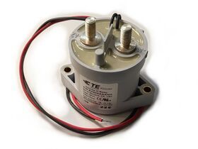
Littlefuse 526 Series (Motors, Array, Charging) TL, Edison TJN-100 (Main) TR, Riedon SSA-250 Current Sense BL, Kilovac EV200 Contactor BR
Out of all these the 15-50a fuses were definitely the hardest to find as I wanted all of these fuses to have the same form factor and be able to mount via bolted joint. The Littlefuse 526 series is the only one online that is able to meet these requirements and it just so happens to be designed specifically for electric vehicles.
Below is the design that I came up with for the final bus bar network.


Assembly
For the assembly I chose to use clinch nuts on the copper that allow for the nuts to be embedded into the bus bars and reduce the need for you to use a wrench on each side to tighten the fuses in place.


All the waterjet components as well as clinch nut installation
For the tray I designed it to be 3D printed in two parts out of PETG. There is a M3 Heat-set insert and datum pin for each bus bar to keep everything aligned as well as walls between all the bus bars to prevent shorting. As metric hardware is something we don't use fairly often I also included the allen key and socket sizes needed to do repairs embossed into the print.


In its current state it is nearly done but is still waiting on the current sensor as well as routing all the wires and hooking it up into our battery pack. I think it should work well and will be the standard for our team's battery pack design moving forward.
Conclusion
Overall I really enjoyed this project and am glad that it greatly simplifies the design of our battery pack. I used quite a few CAD techniques I hadn't before to model the bus bars and tray. I am quite proud of how everything turned out as all the parts went together perfectly and the final design ended up being pretty clean.
To see some of the other solar car work that I've done as well as my other projects click the links below.
Caden Kraft Newsletter
Join the newsletter to receive the latest updates in your inbox.


