In my last SCARA arm project, I had a very frustrating experience designing high torque/high accuracy gearboxes for the Nema 23 stepper motors I used. Ideally for that project I could have used fancy off the shelf servos or QDD (quasi-direct-drive) actuators like the MIT Mini Cheetah. The problem with these is that they generally cost ~$500-1000 each, which is something I can't really justify for my projects.
This led me to want to develop my own QDD actuator with a heavy focus on keeping the cost low, both on the parts and tools needed to create one.
What's a QDD actuator?
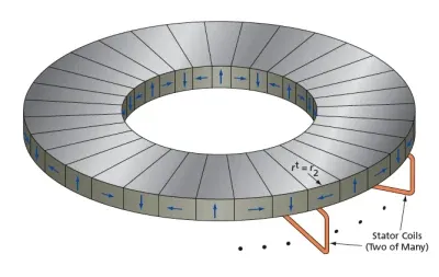
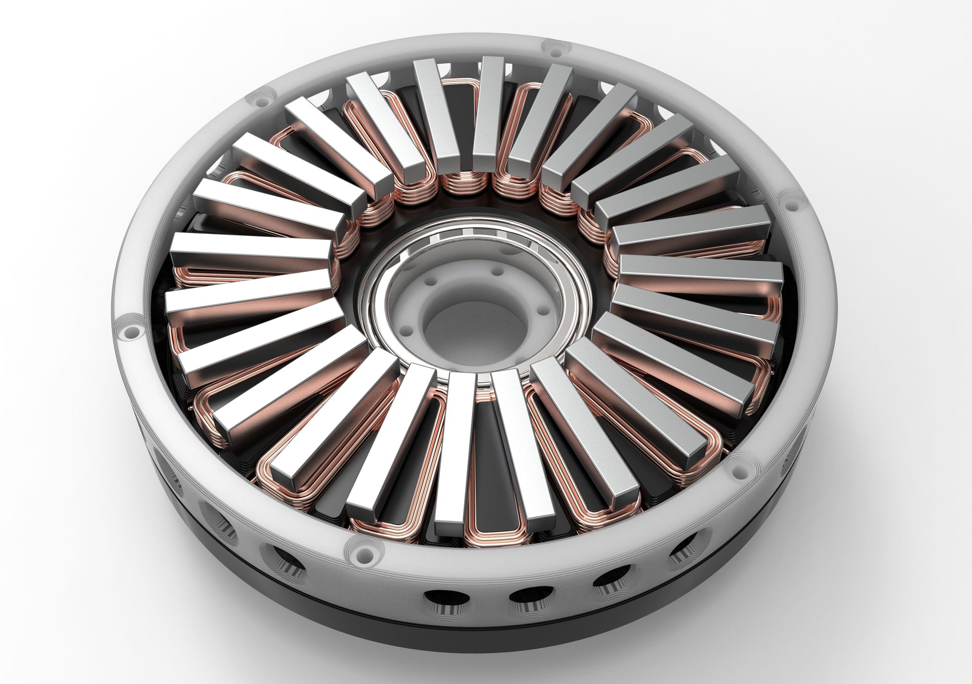
A quasi-direct-drive actuator is a term referring to a type of actuator initially popularized by MIT with their Mini Cheetah actuator.
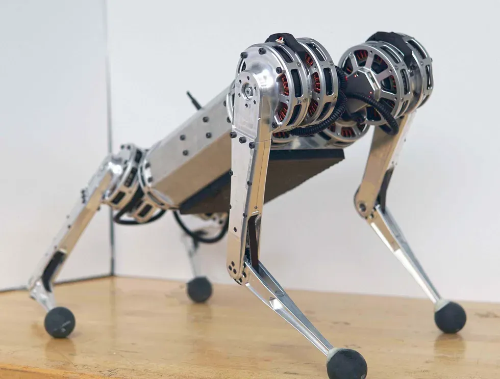
They generally consist of a radial BLDC motor with a gearbox reduction inside the stator that can heavily increase the torque while being extremely space efficient in their height. They are most famously used inside quadruped robots like the MIT Cheetah.
For this actuator, I don't have a final plan on what I am going to use it on just yet, but I wanted to create a platform that I could easily use and modify for my future projects.
Project Goals
The main goals I had for this project are as follows:
- Low cost, less than $80 per actuator
- Fully 3D printed, every single custom part is 3D printable. No machining, laser-cut metal parts, etc
- 10Nm of holding torque
- Easy to interface into my projects
Some of these goals present some challenges, namely needing to make the rotor and gearbox fully 3D printed.
Rotor Design
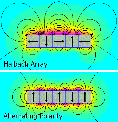
Every actuator design I have found online uses some sort of iron/steel backing behind the magnets in order to direct the flux of the magnets inside towards the stator. If my rotor is going to be made out of plastic, I wanted to try and make a design without a ferrous backing that doesn't give up significant performance.
To solve this, I chose to use a Halbach array like my previous axial flux motor project that was also fully 3D printed. This time I actually wanted to quantify the performance that I was leaving on the table by not using an iron backing.
I used FEMM to create magnetic simulations where I measured the static torque at a fixed angle for all three phase pairs of the motor. Then I created 4 different configurations to test how the different rotor designs affected performance: Halbach array with an iron backing, Halbach array with no iron, normal array with iron, and normal array without iron.
The results of these simulations are below.
| Rotor Config | AB Torque (Nm) | BC Torque (Nm) | AC Torque (Nm) | Average Torque (Nm) | % From Max |
|---|---|---|---|---|---|
| Halbach Iron | -0.915 | -0.310 | 1.824 | 1.017 | 100.000% |
| Halbach Ironless | -0.832 | -0.207 | 1.748 | 0.929 | 91.381% |
| No Halbach Iron | -0.953 | -0.293 | 1.540 | 0.928 | 91.328% |
| No Halbach Ironless | -0.791 | -0.243 | 1.175 | 0.737 | 72.455% |
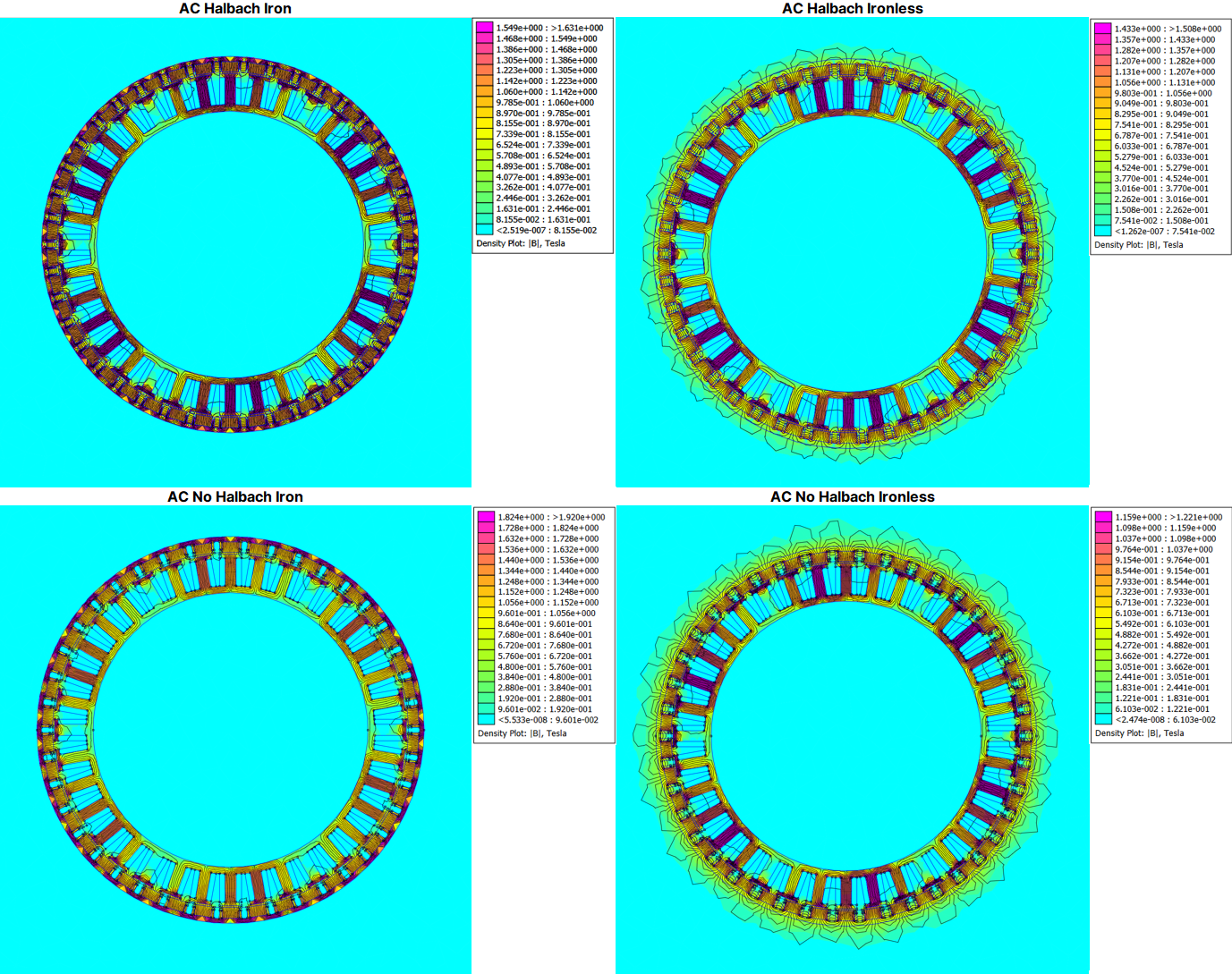
These results were very interesting to me. Not only did the Halbach array have nearly identical performance to an iron-backed rotor, using both gets you a 9% bump in torque, which I would not have expected. This also goes to show how much performance I would be leaving on the table if I just used plastic parts without a Halbach array.
I also want to stress that I don't have a ton of experience in magnetism so if anyone has feedback on these simulations or tips for what I could change I would love feedback!
Using a Halbach array instead of an iron backing will also have much lower rotational inertia compared to an iron backing which is important for an actuator designed to quickly change directions.
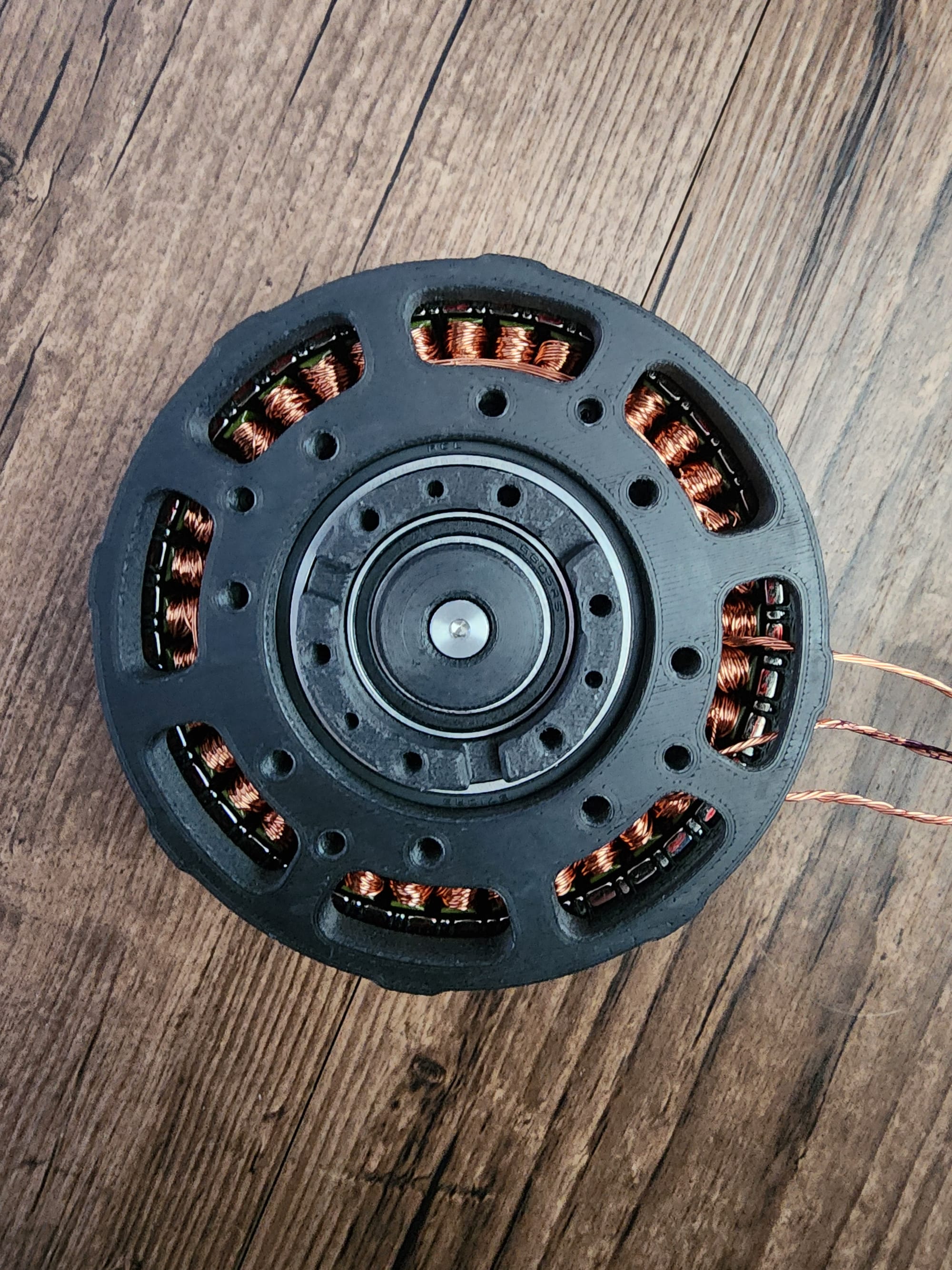
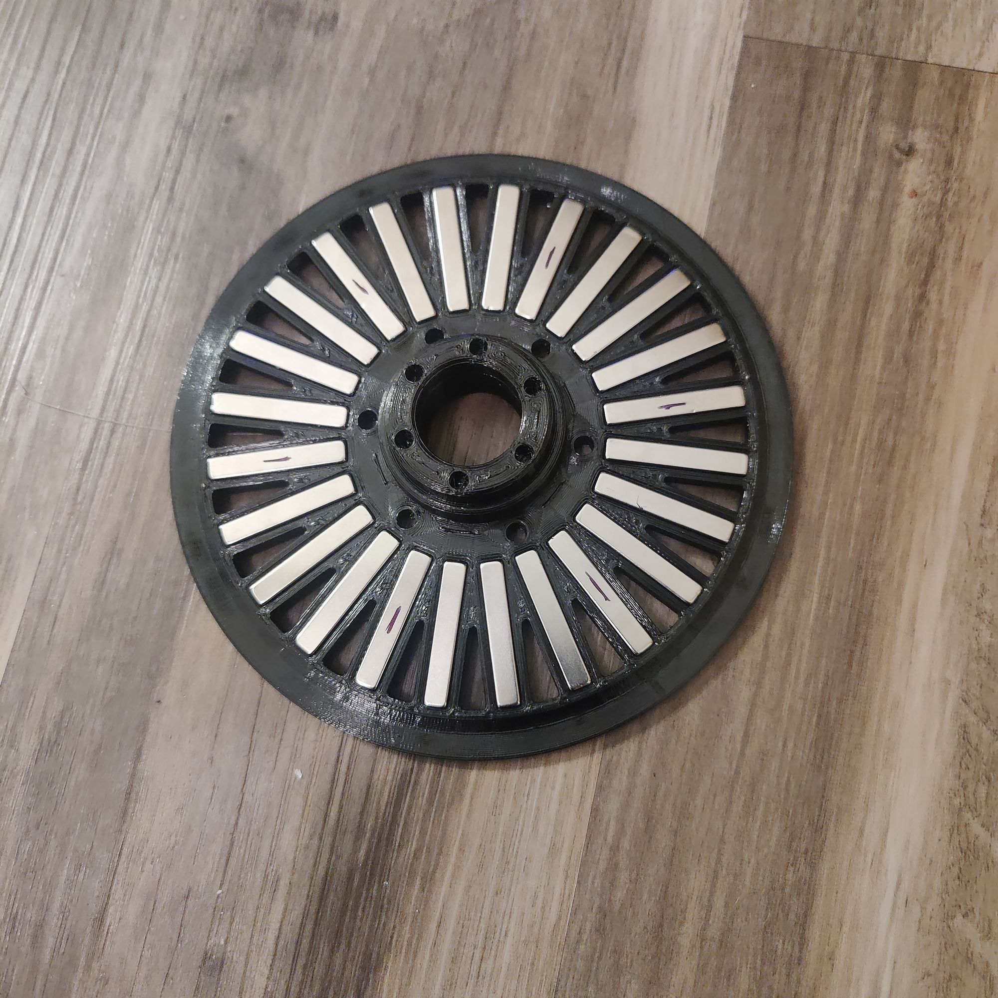
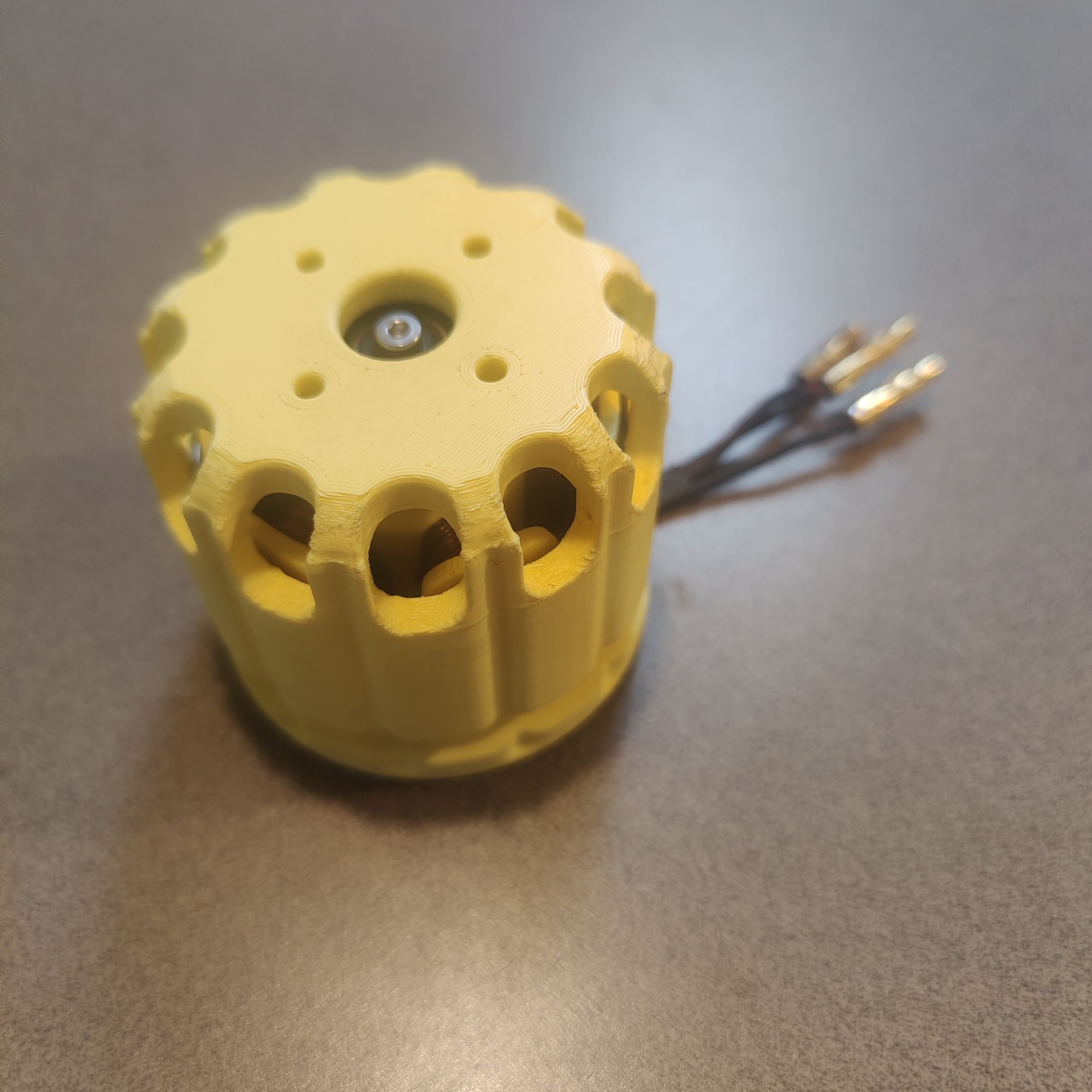
Below is the final rotor design I came up with as a result of these simulations. As you can see, the magnet array is very dense with 42 12 x 5 x 3mm N52 magnets for the main pole pairs, and 42 1/2 x 1/8 x 1/16 N50 magnets for the Halbach pairs, both of which have a 0.7mm air gap to the stator.
Gearbox Design
The next big hurdle I had to overcome was designing a gearbox capable of handling the high expected torques of this actuator made out of 3D printed plastic parts. I chose to go with a planetary gearbox as it can usually be made more compact as compared to cycloidal or harmonic gearboxes.
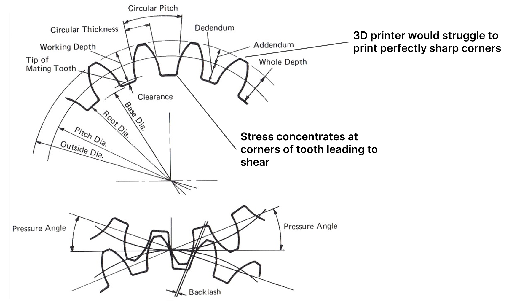
The problem with 3D printing gear teeth is that most gear tooth profiles require sharp edges and because 3D printers extrude plastic out of a round nozzle, you are always going to have some sort of corner radius no matter how small. Plastic gears using traditional spur gear teeth also tend to run into shearing issues as the teeth are quite small and tend to fail at stress concentrations near the base of the tooth.
This made me rethink how I approached defining my tooth profile. The work I did on my previous cycloidal drive projects made me wonder if there existed planetary gearboxes that used cycloidal 'tooth' profiles.
Searching around I found out about pygeartrain, a Github project that can generate all sorts of crazy gearbox designs from mathematical functions. This can lead to some really wacky planetary designs such as this one. All credit for this goes to Eelco Hoogendoorn and he has a ton of other cool projects!
The problem is that pygeartrain was designed simply as a way to test and visualize gear profiles and not to create anything you could actually export to a 2D/3D model and implement into a design.
This led me to create a version that can create the cycloidal planetary gearbox profiles, allow you to give them actual dimensions, as well as create export files for actually modeling them out in SolidWorks. I also added functionality for creating helix and double helix versions of the cycloidal gear tooth profile.
Below is my Github repo where you can mess around creating your own wacky gear profiles with a full guide to turn those into 3D models.
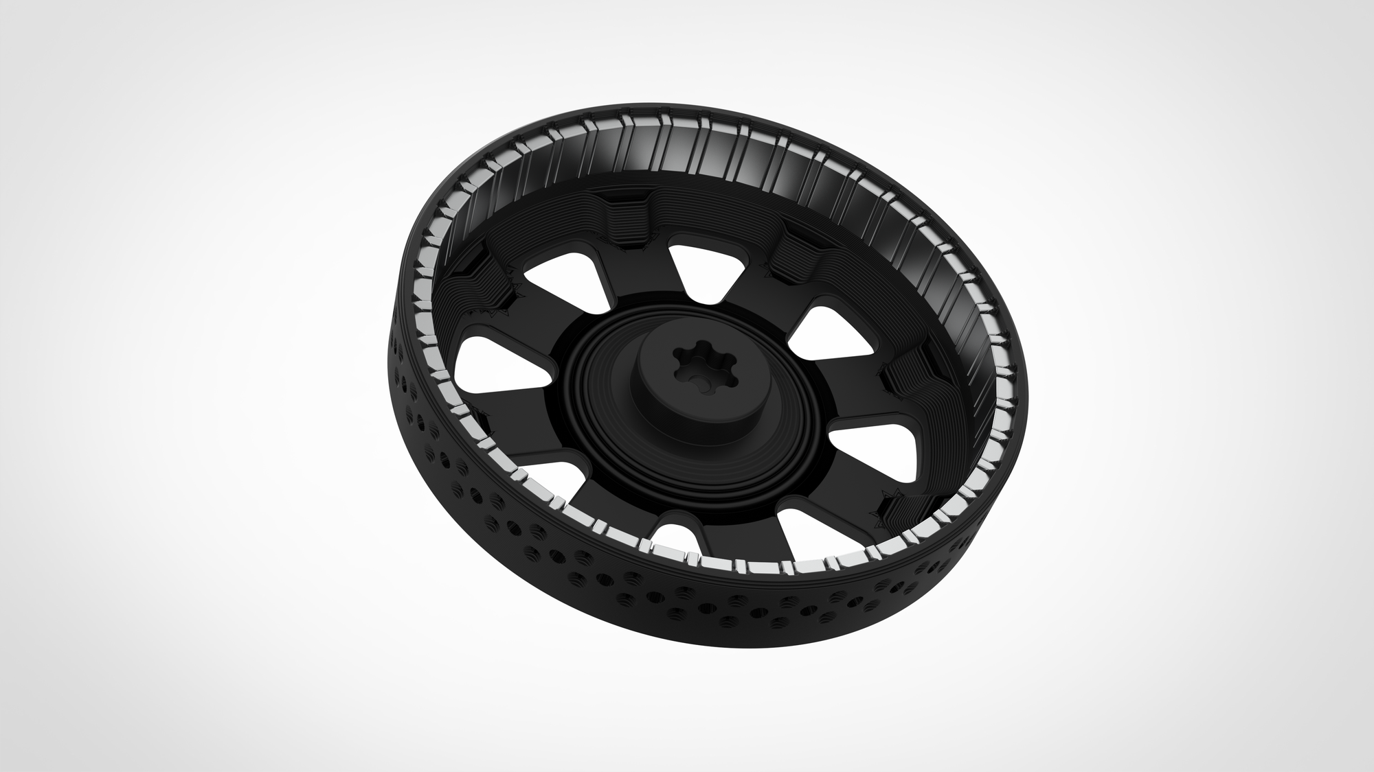
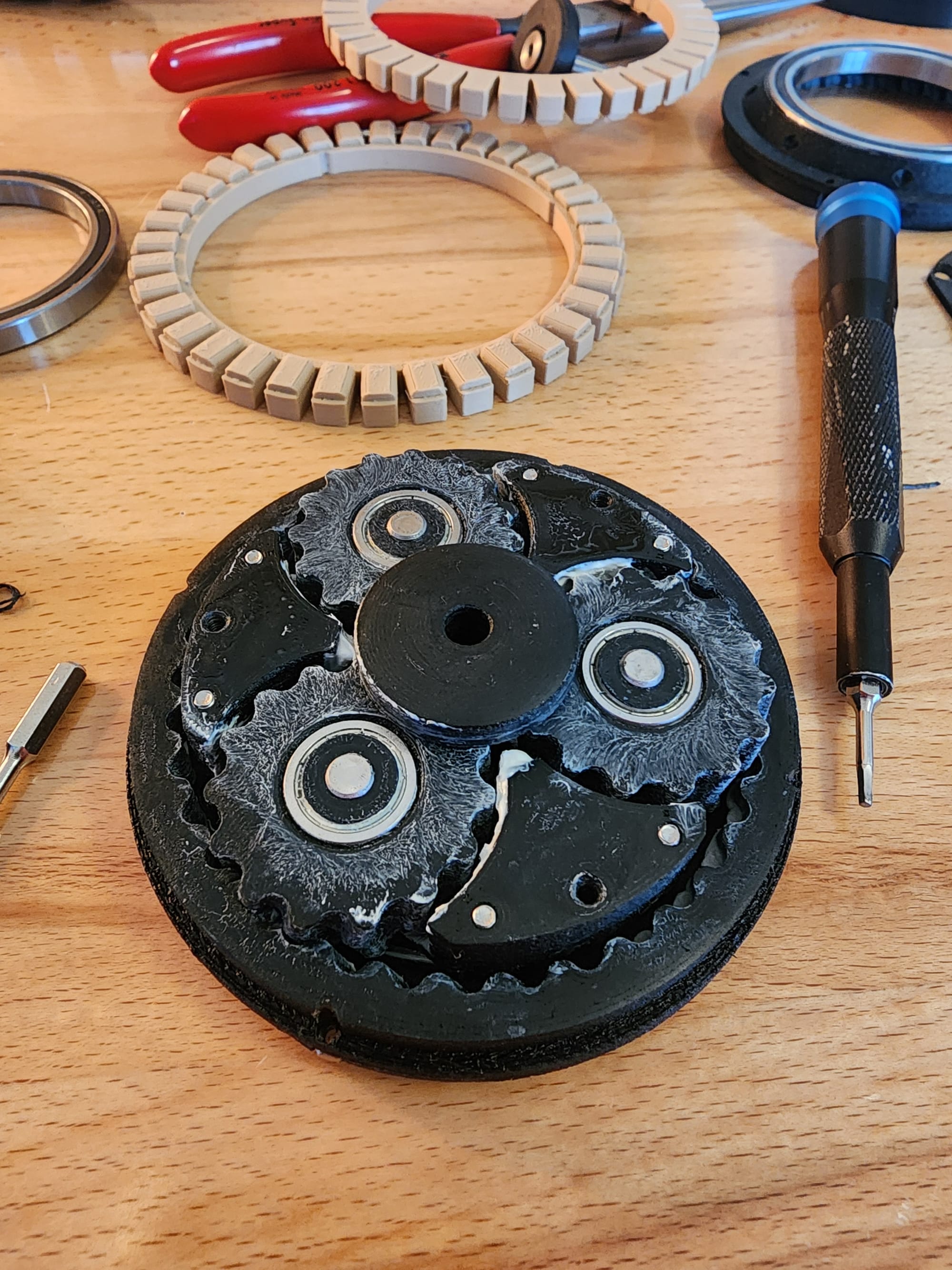
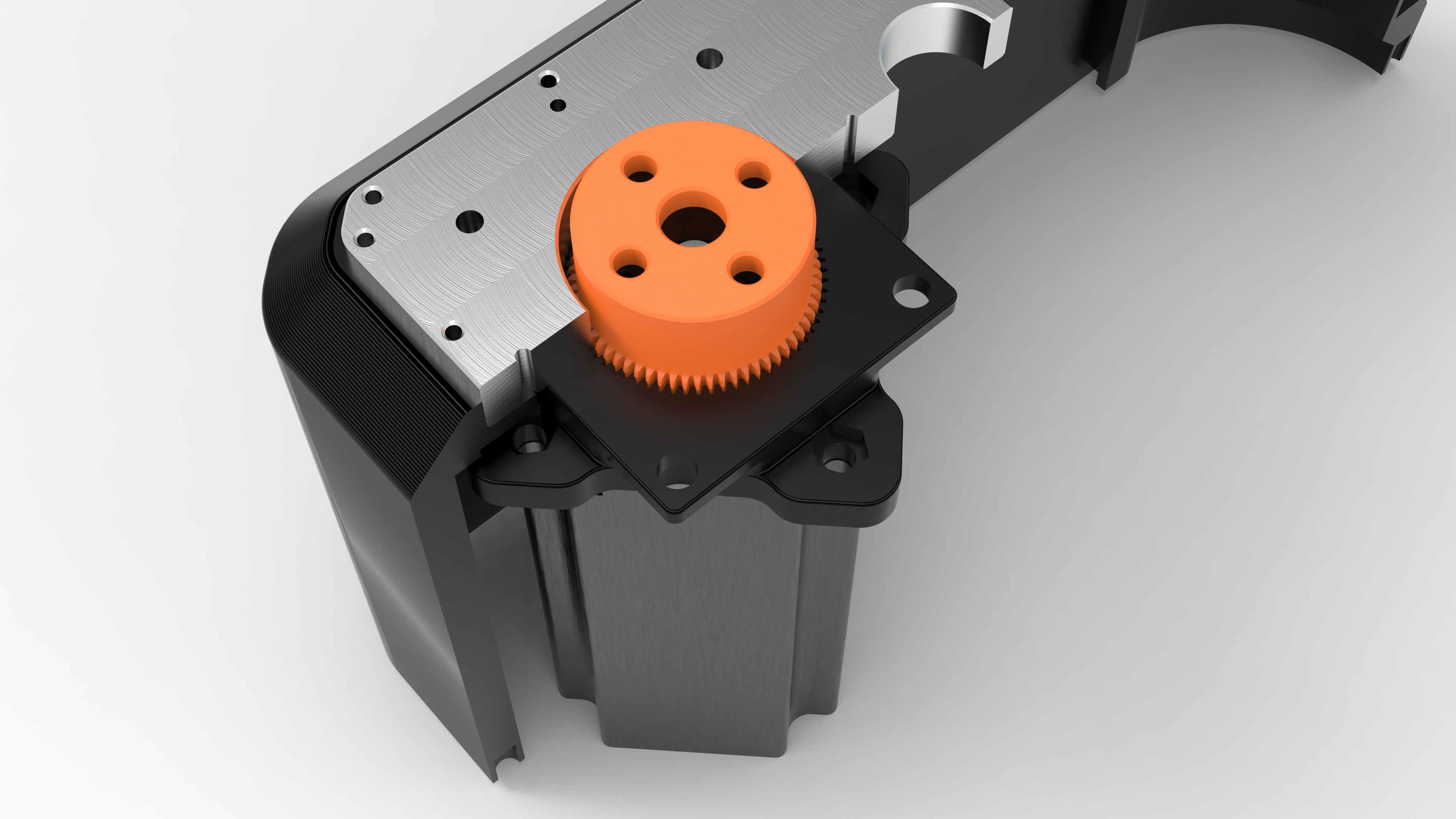
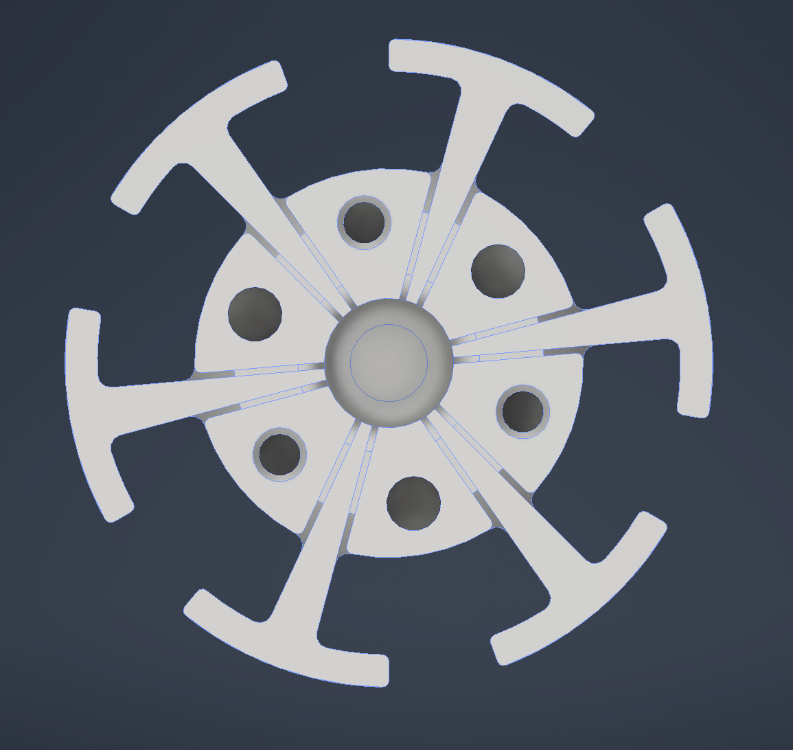
For this project I chose to create a 7 to 1 gearbox visualized below.
As you can see with this gear profile, not only is there constant contact with no backlash due to the profile, you can also see the "teeth" are more like lobes in one continuous outline, which a 3D printer can easily create. Both of these benefits make these gears seem like they should be fantastic for 3D printed gearboxes, and I am honestly surprised I haven't seen anyone try this before.
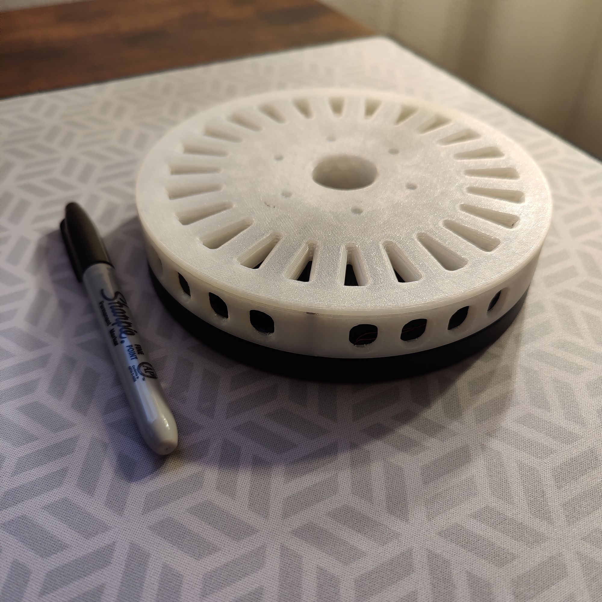
Creating the integrated design into my actuator from these exports was slightly more complicated. Below is the final gearbox module that goes through the center of the actuator.

Stator and Windings
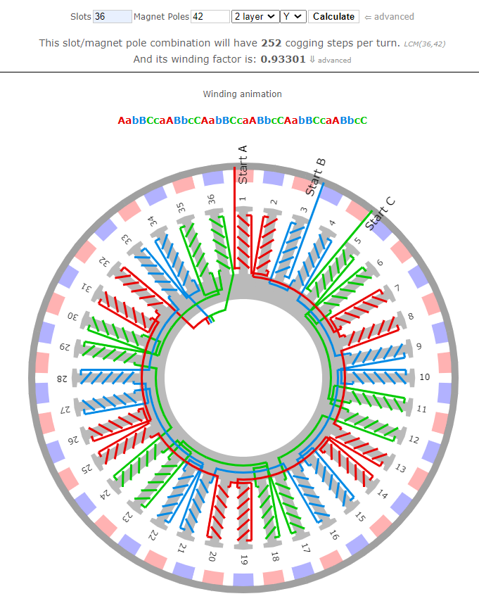
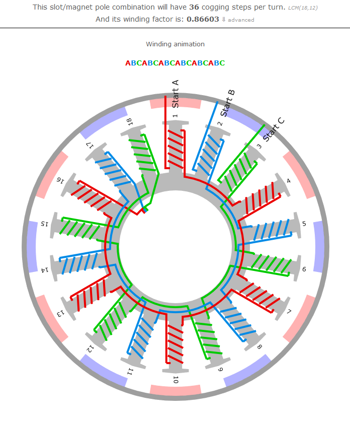
For the stator, I chose to use a 10010 stator as they are cheaply available online and fell roughly within the size I wanted the stator to be. This is a 36 slot stator so I chose to use this winding configuration that I got from the bavaria direct winding calculator. For the windings, I chose to do 6 turns (5 full, 1 partial) around each slot, winding 6 strands of 0.4mm diameter wire in parallel.
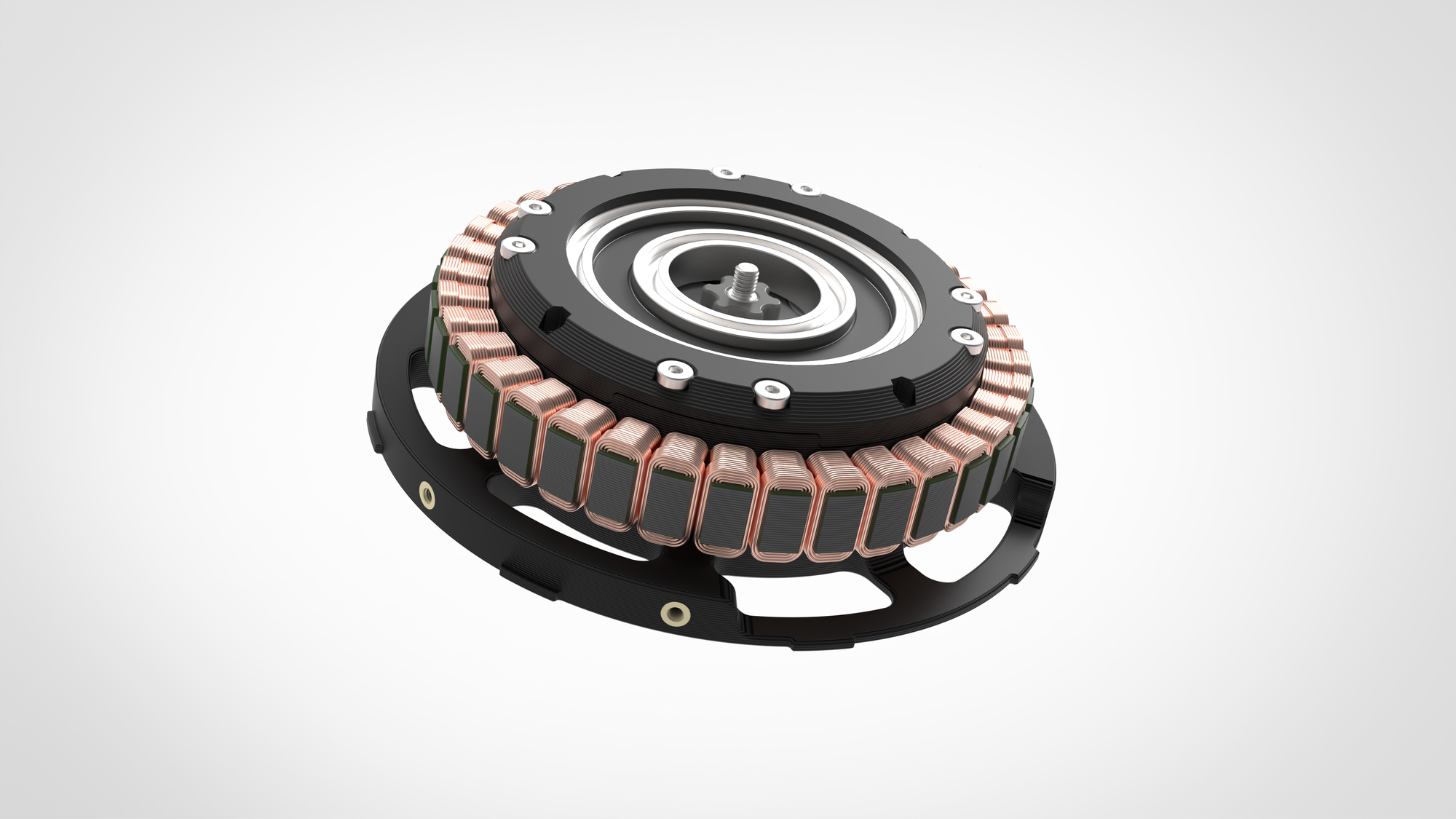
Here is a render showing how the stator is assembled into the clam-shell of the gearbox module.
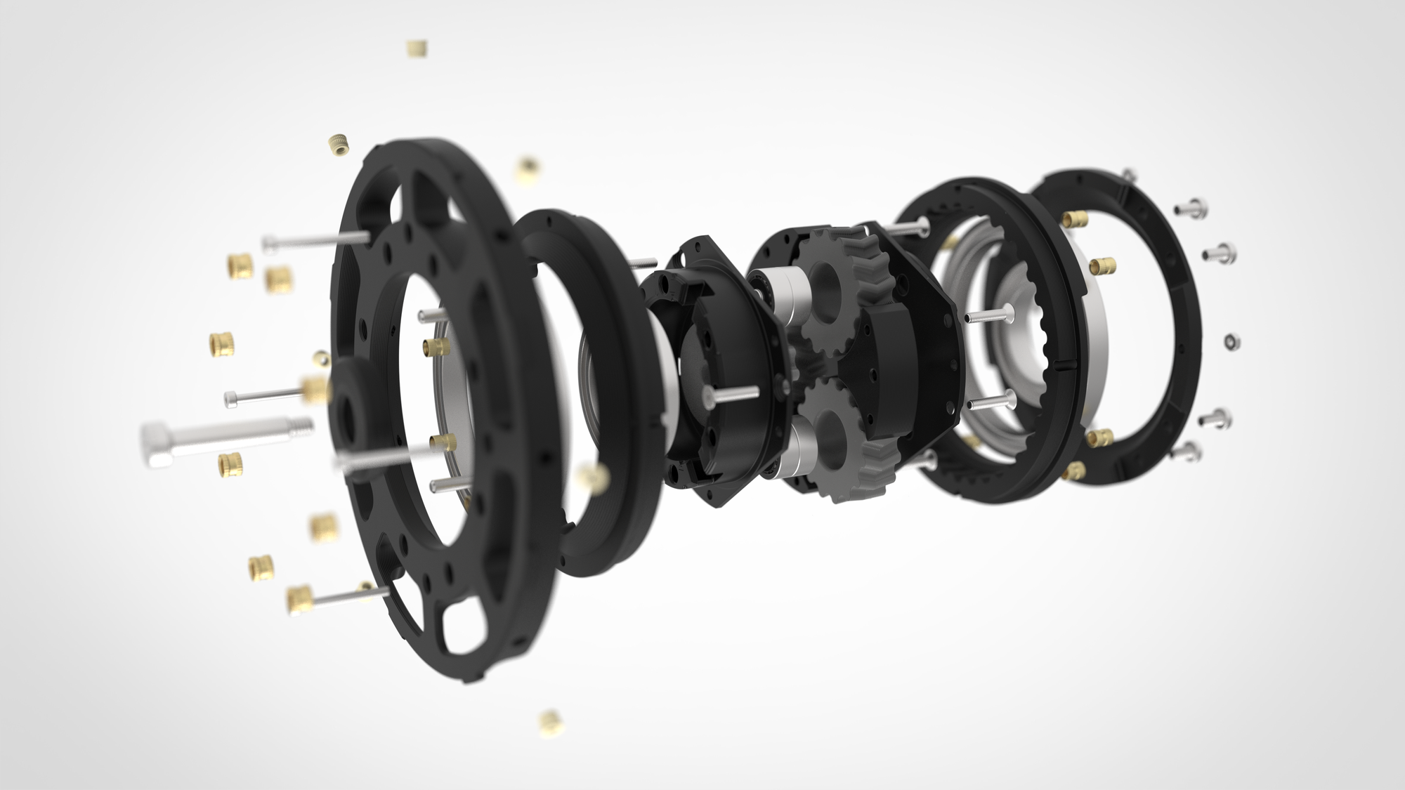
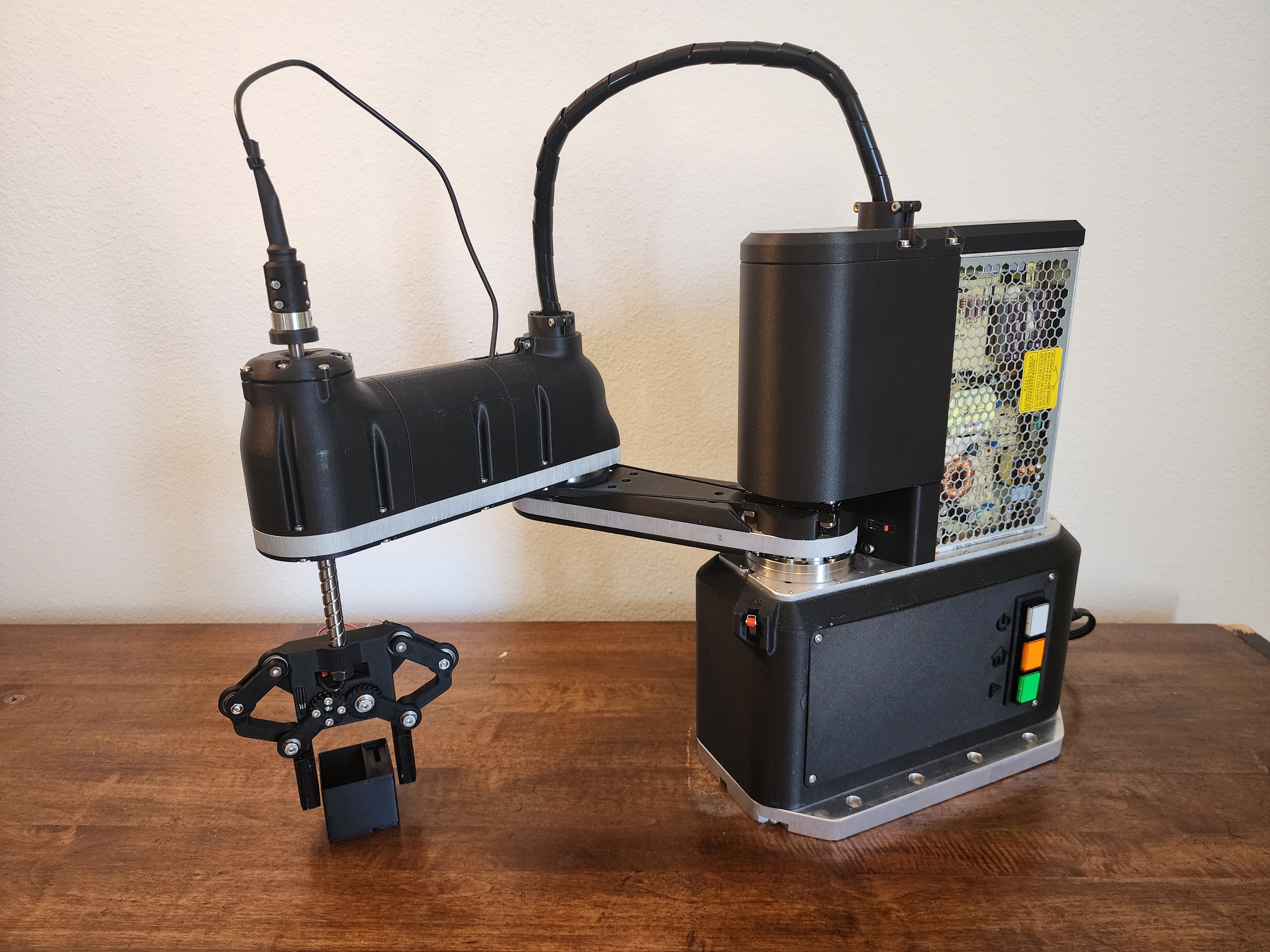
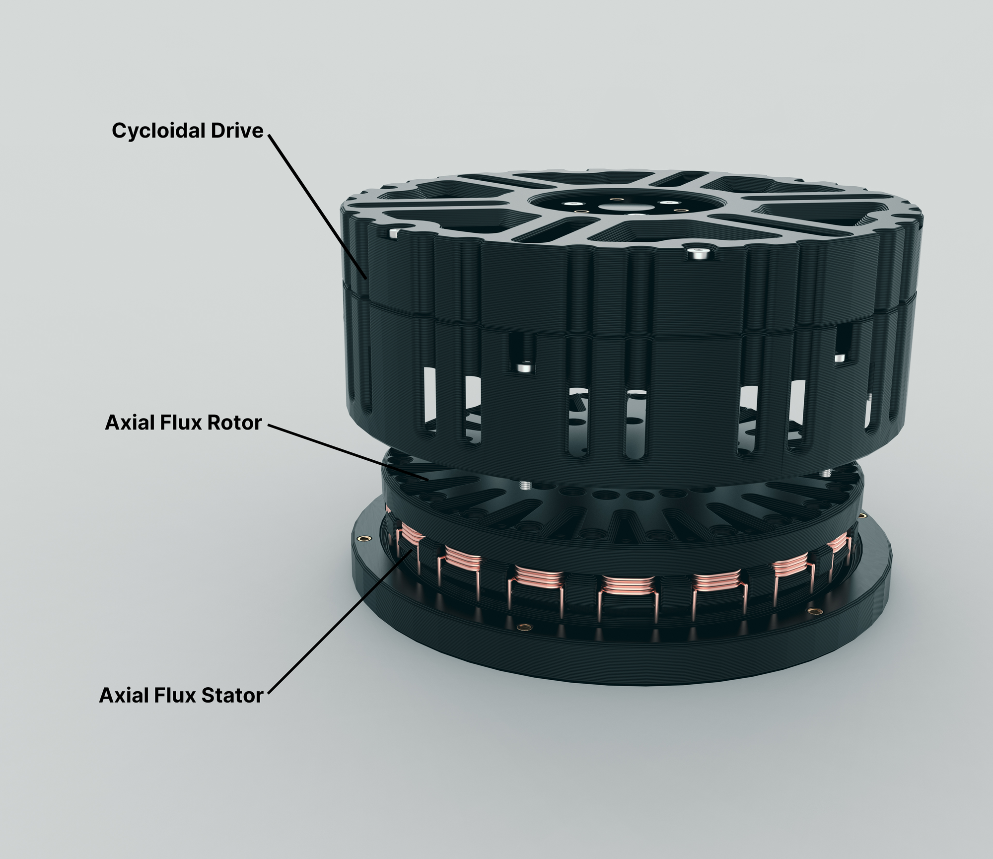
The Final Actuator Design
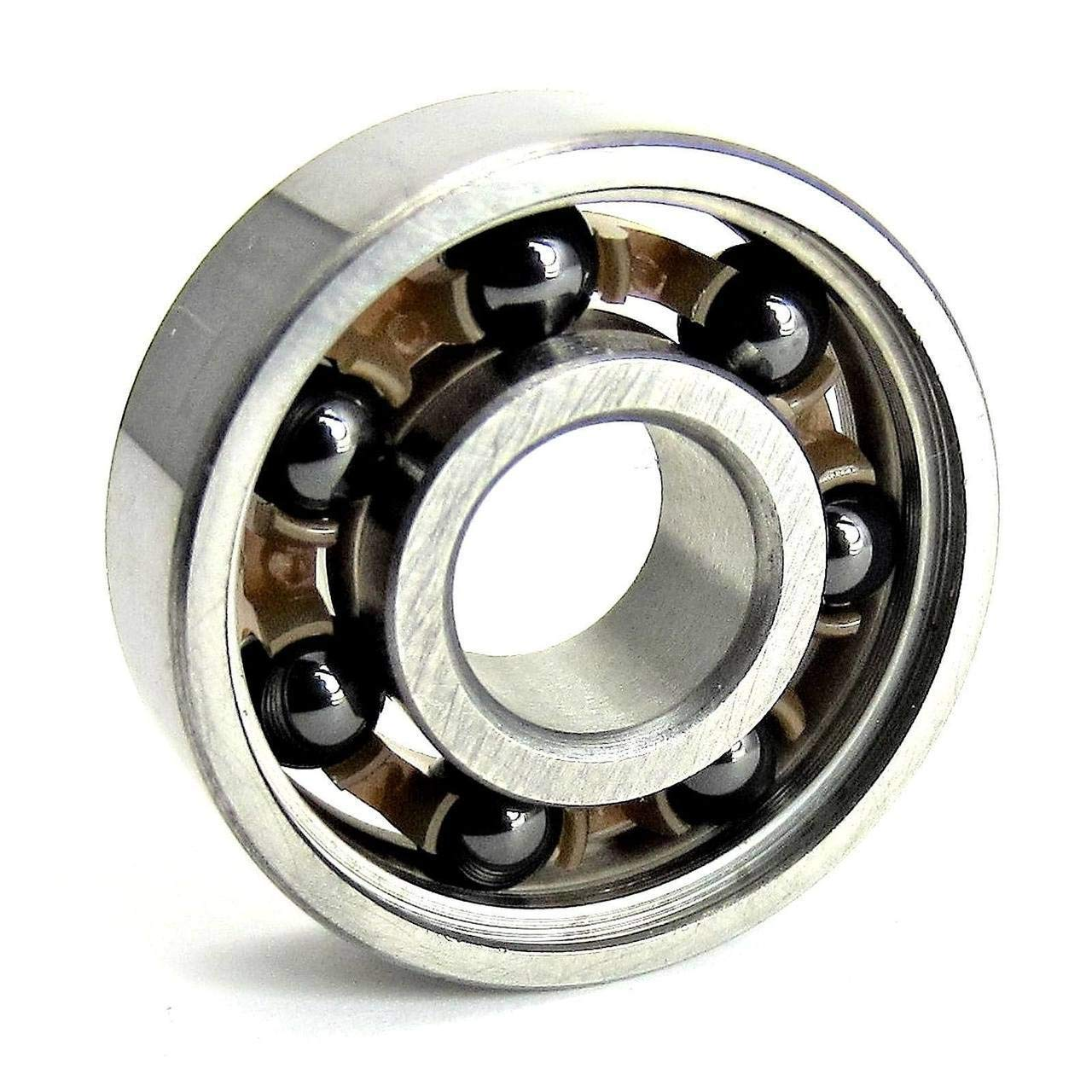
Now that I had designed a rotor, gearbox, and chosen what stator I wanted to use, it was time to put everything together into one cohesive design. I wanted this actuator to have an integrated controller and to keep costs down I chose to go with the MKS X Drive Mini. This is a low cost controller based on the older ODrive 3.6 and has a built in hall effect encoder making it suitable for integrating directly into the actuator.
I would have liked to use a proper new ODrive or a moteus controller, but they are hard to justify as they cost 2-5x more than my entire actuator design for just the controller.
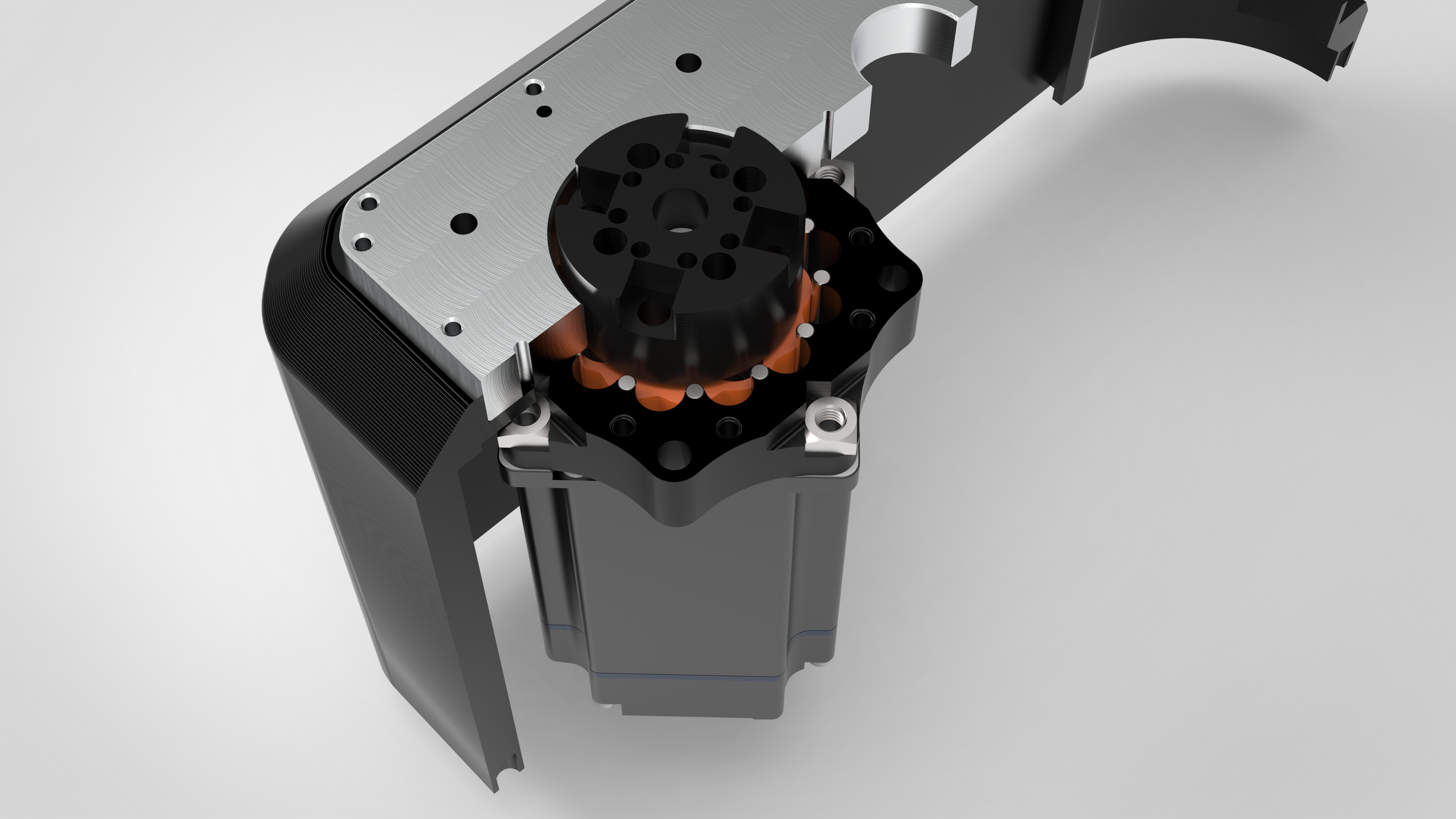
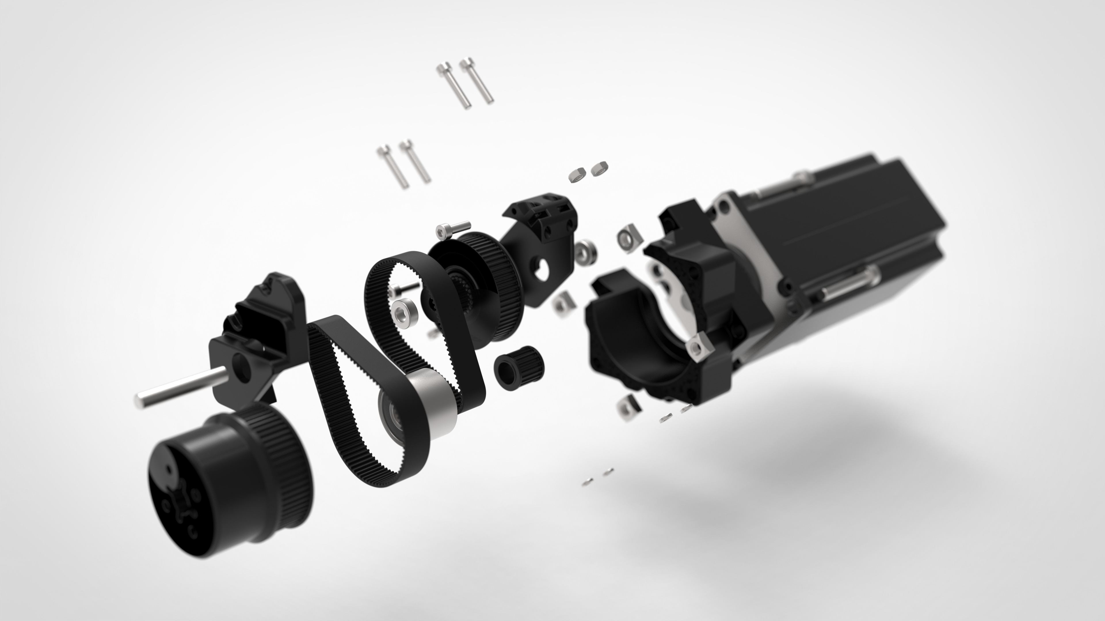
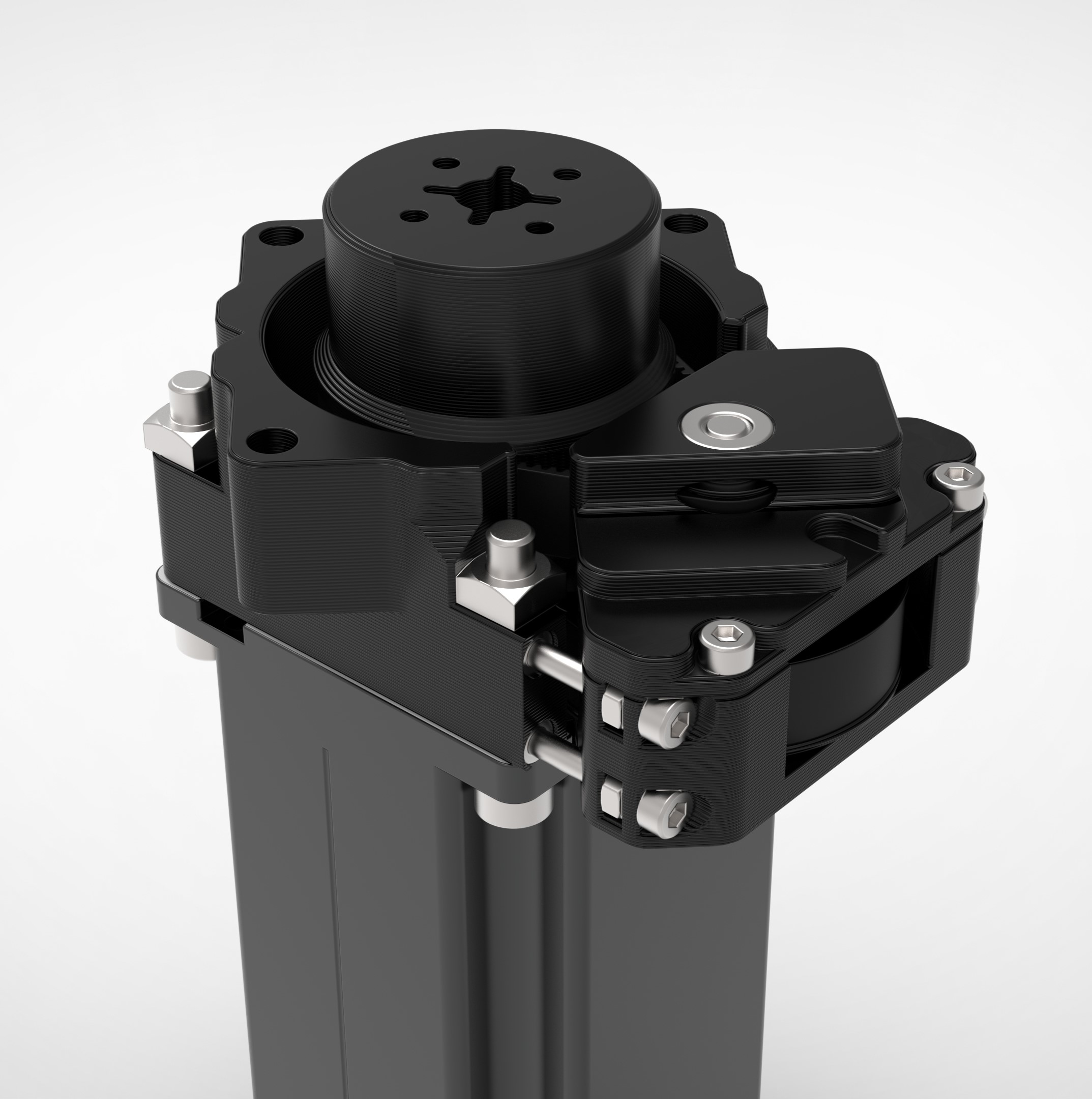
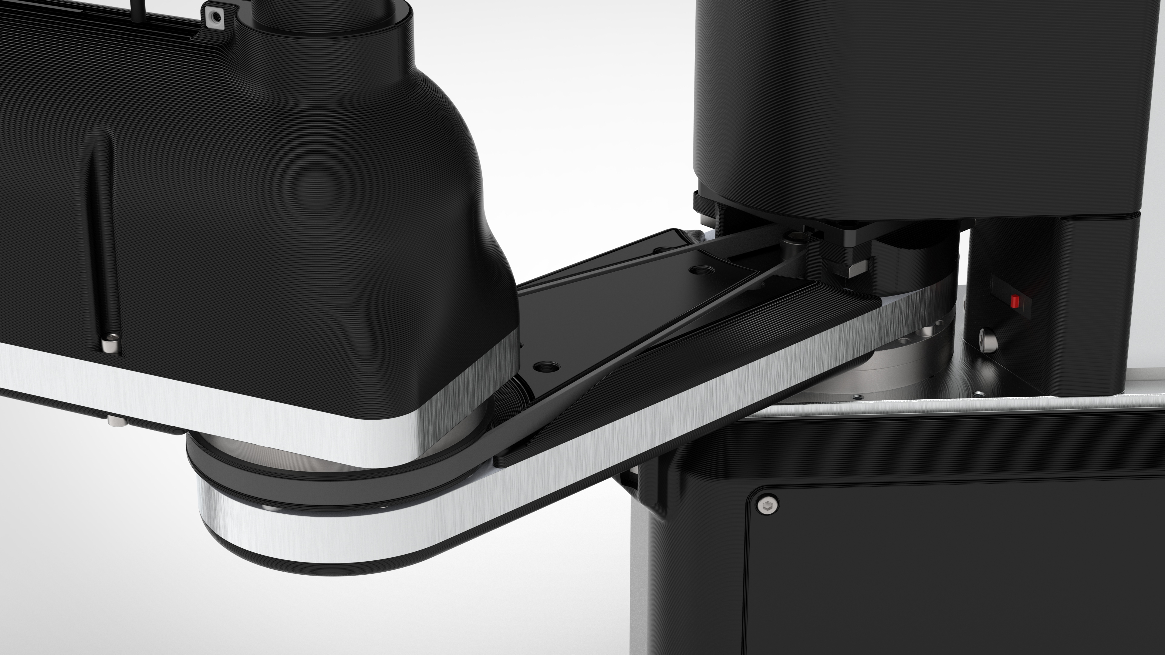
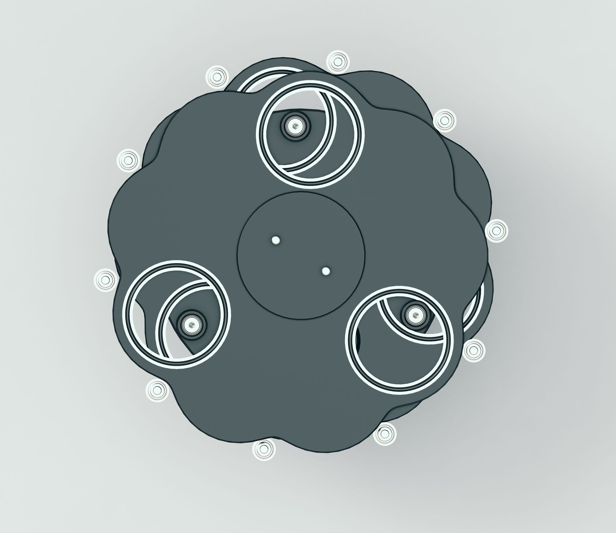
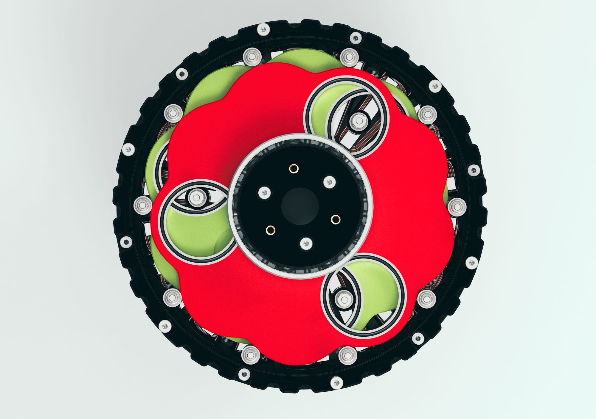
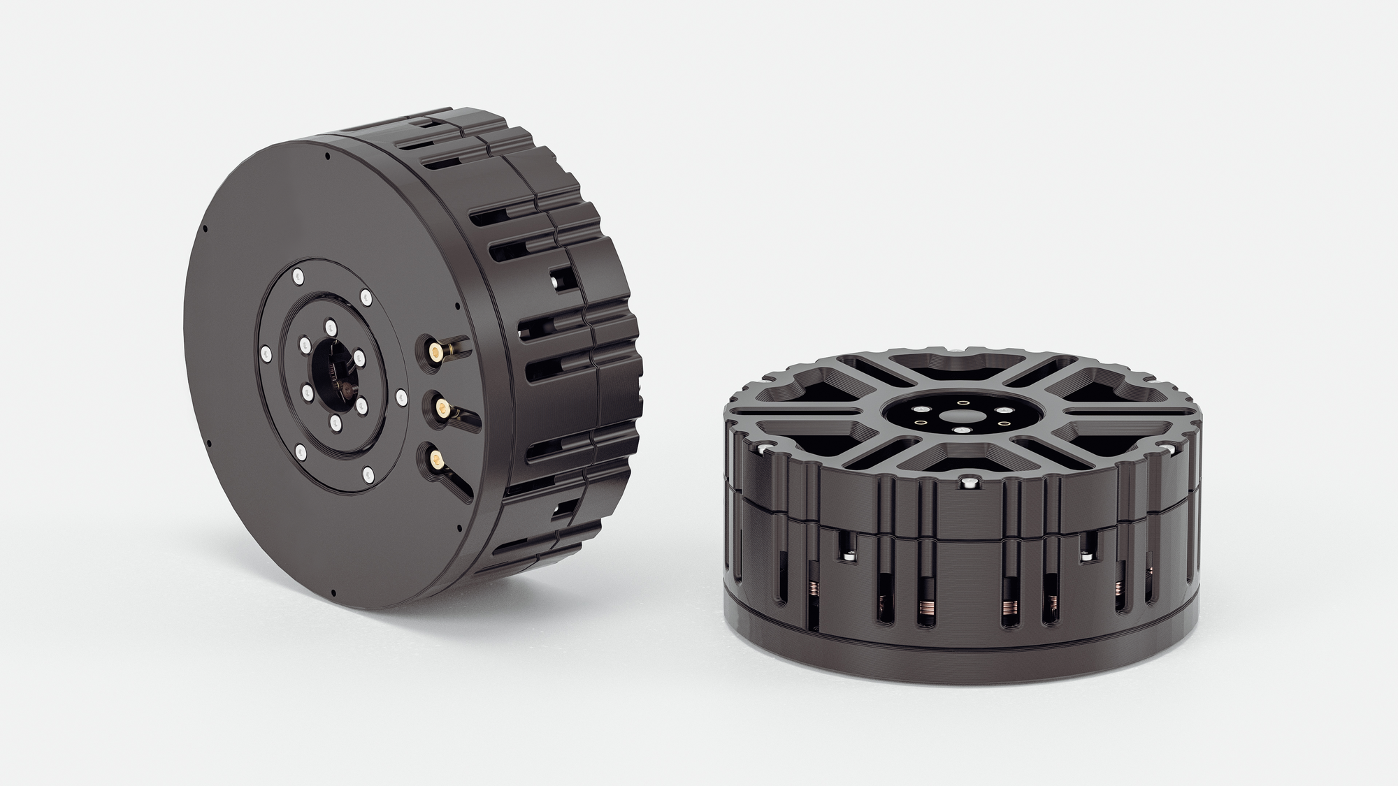
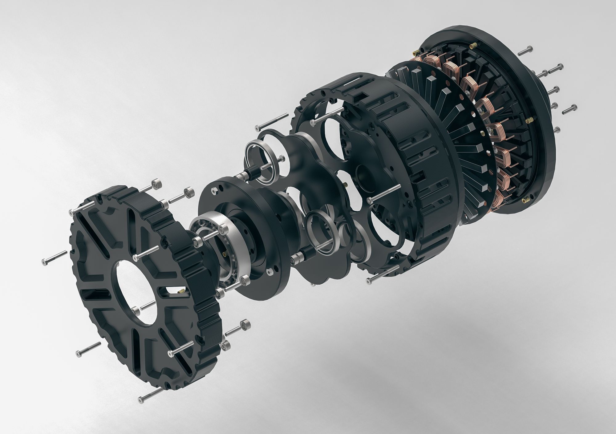
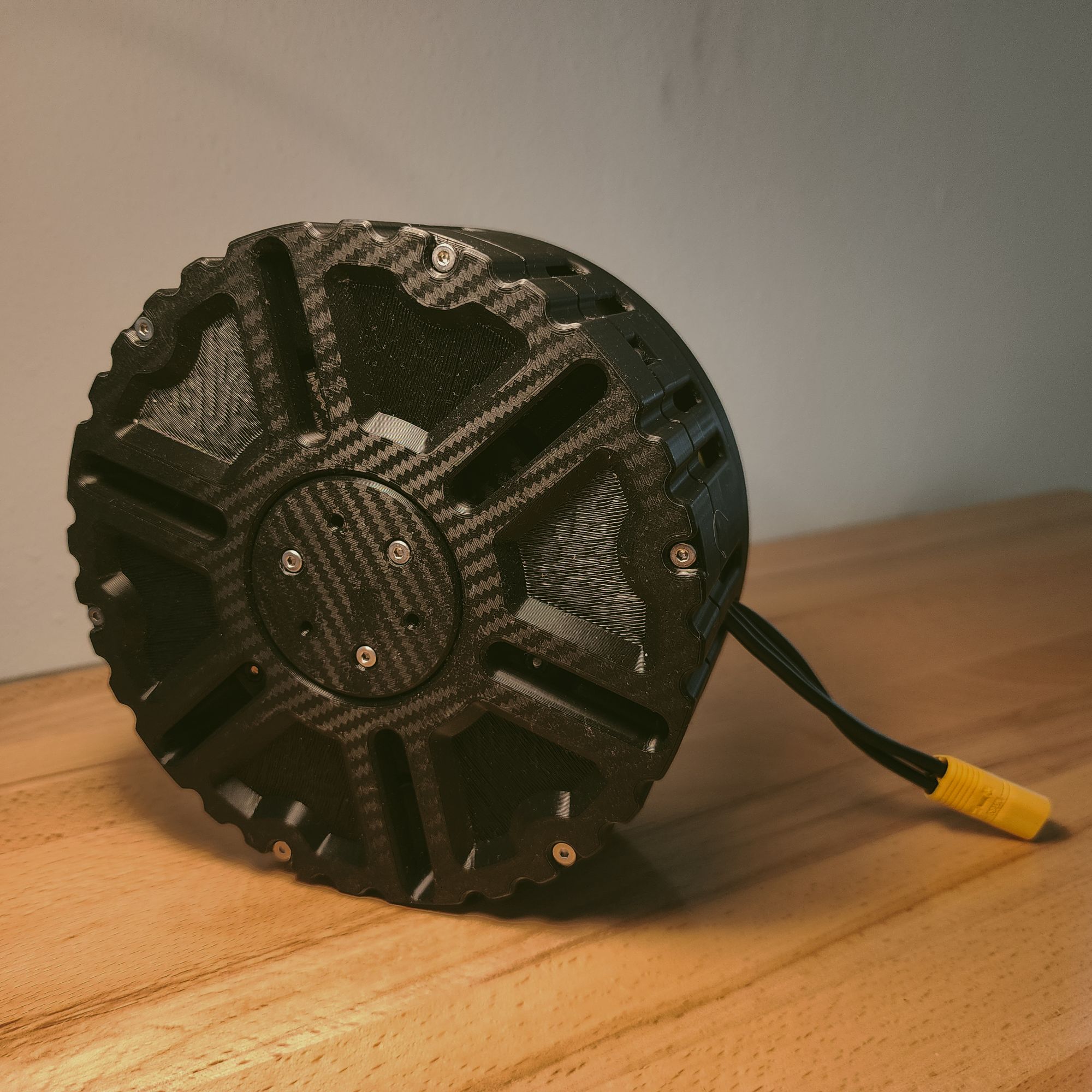
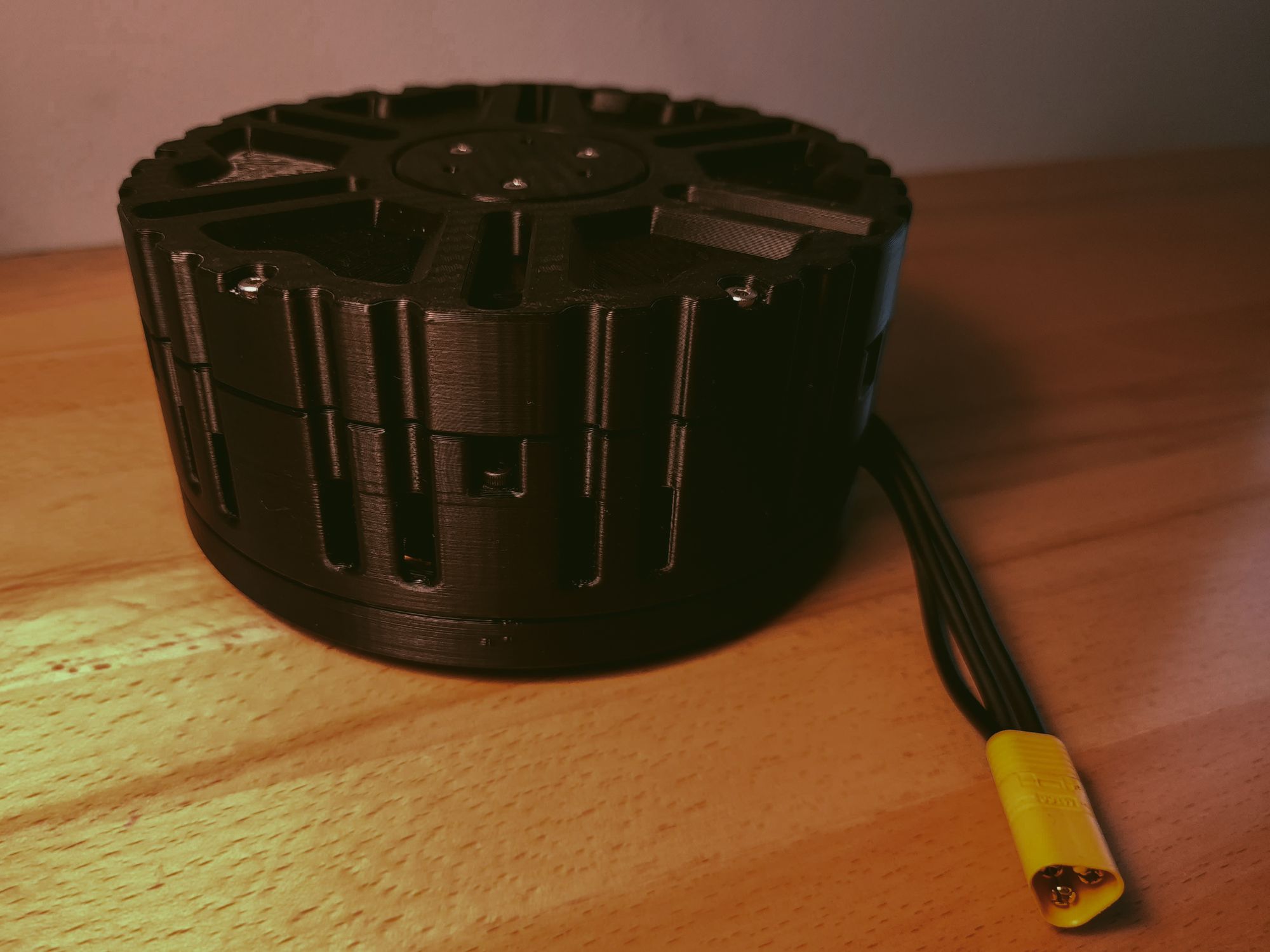
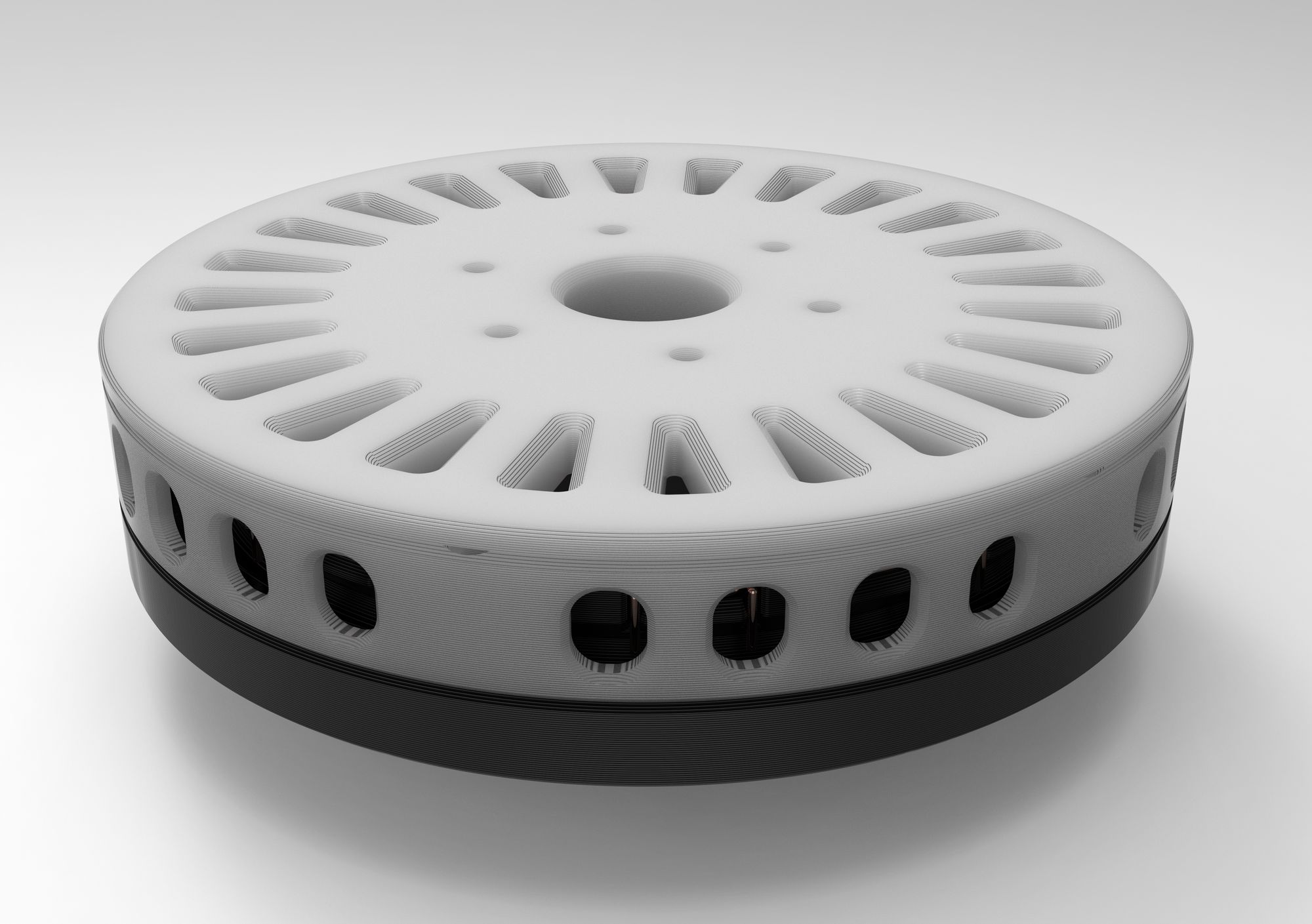
Here are some renders of the final actuator design that I came up with.

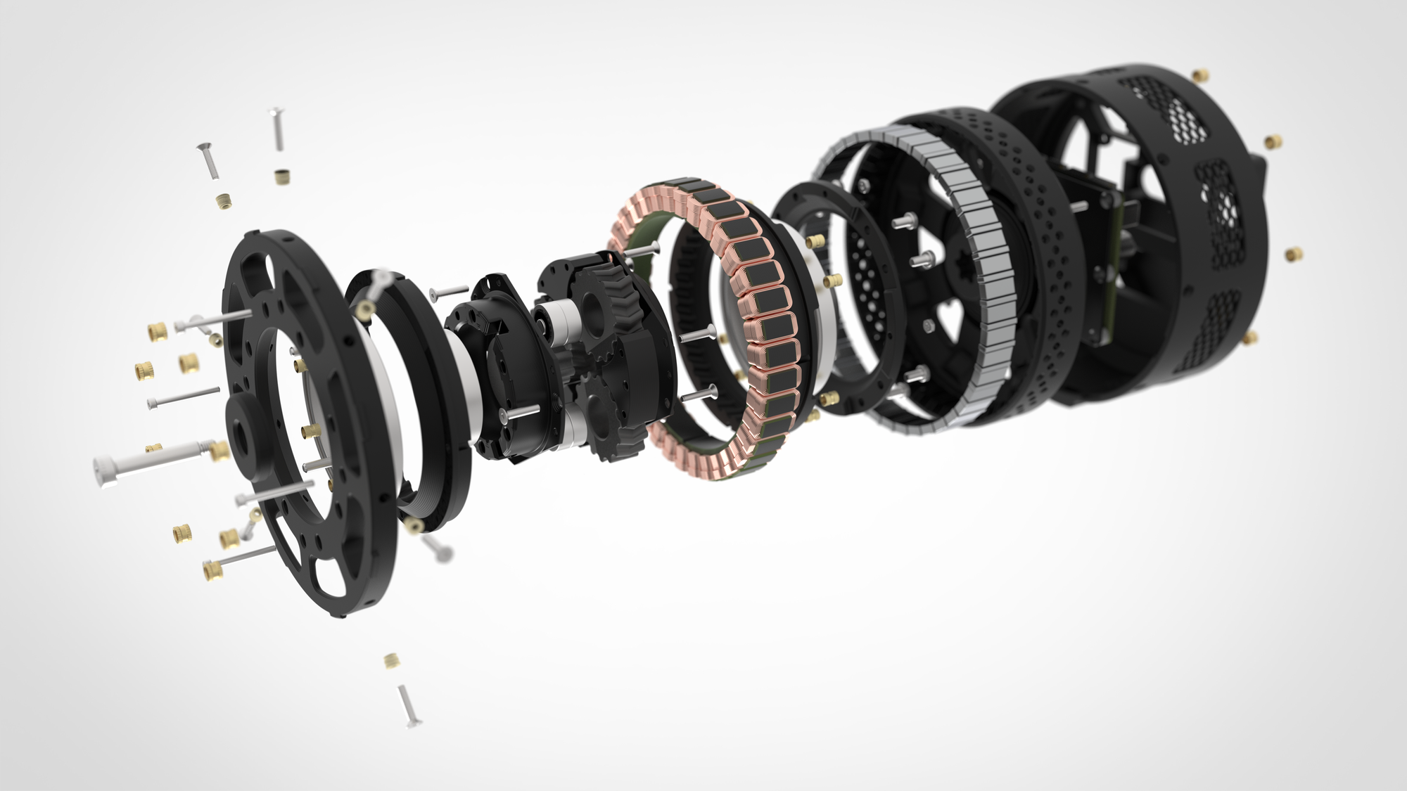
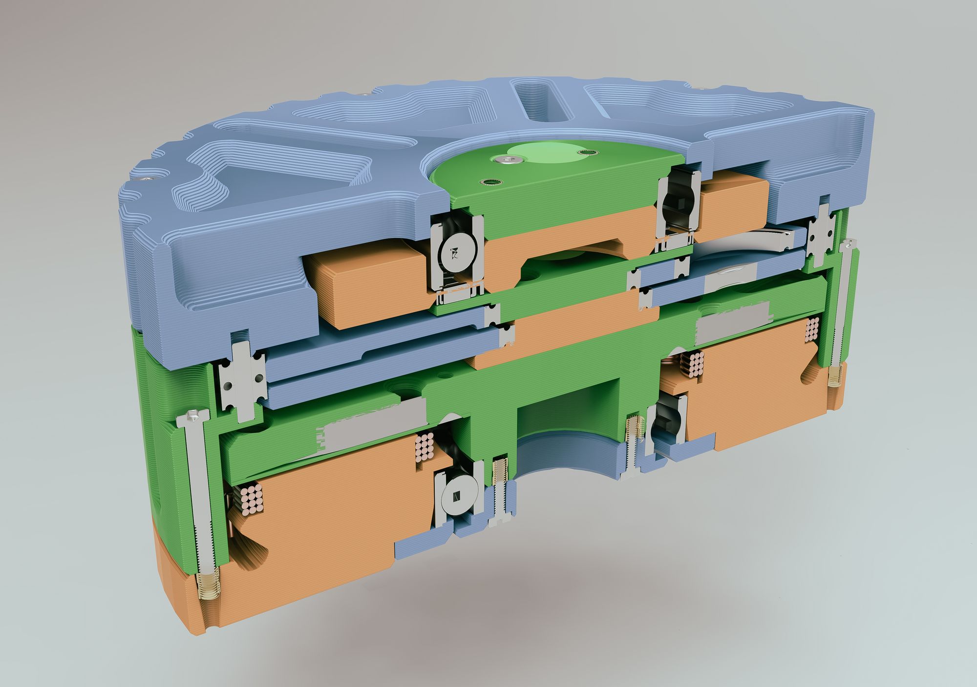
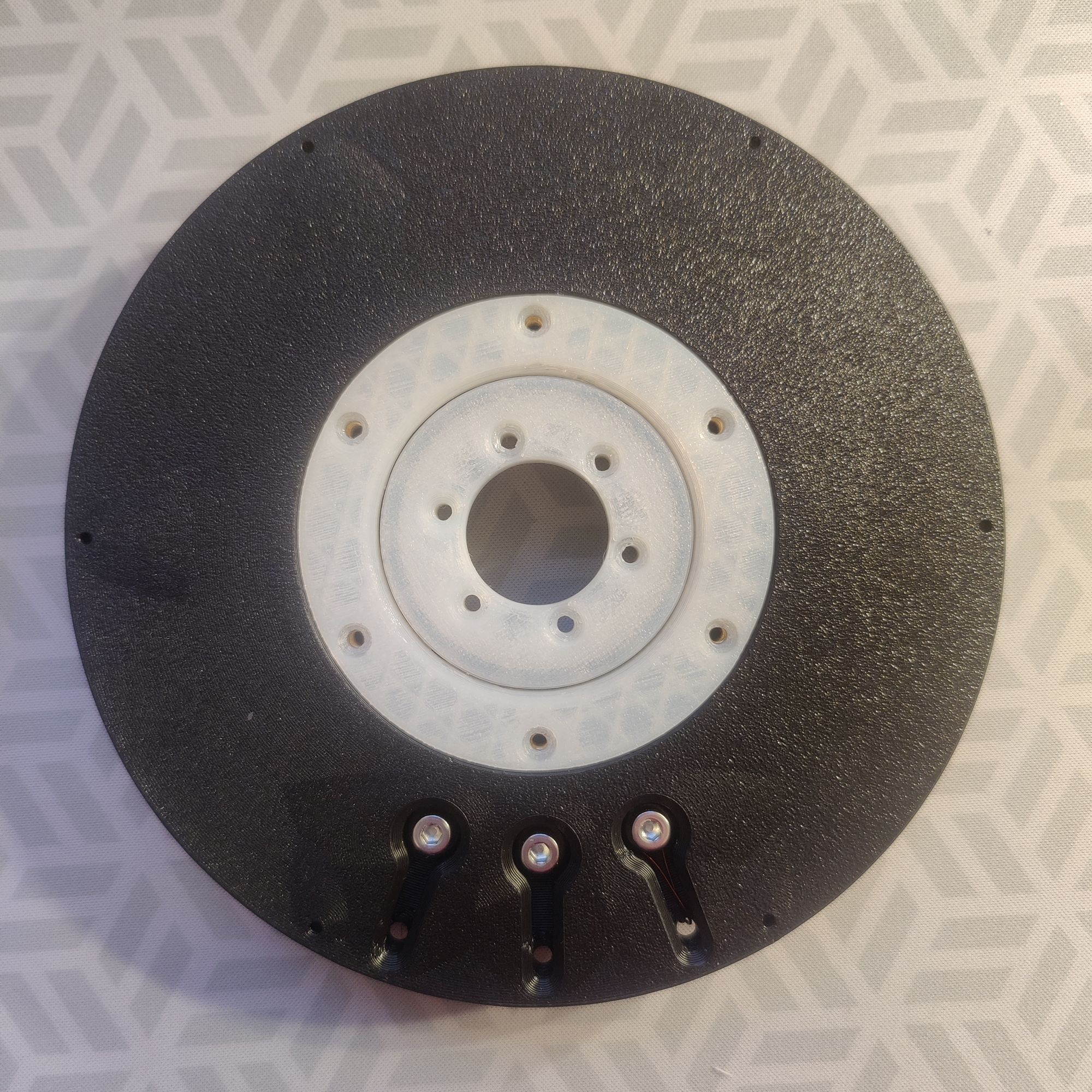
Here is a cross section of the actuator with all the 3D printed components colored.
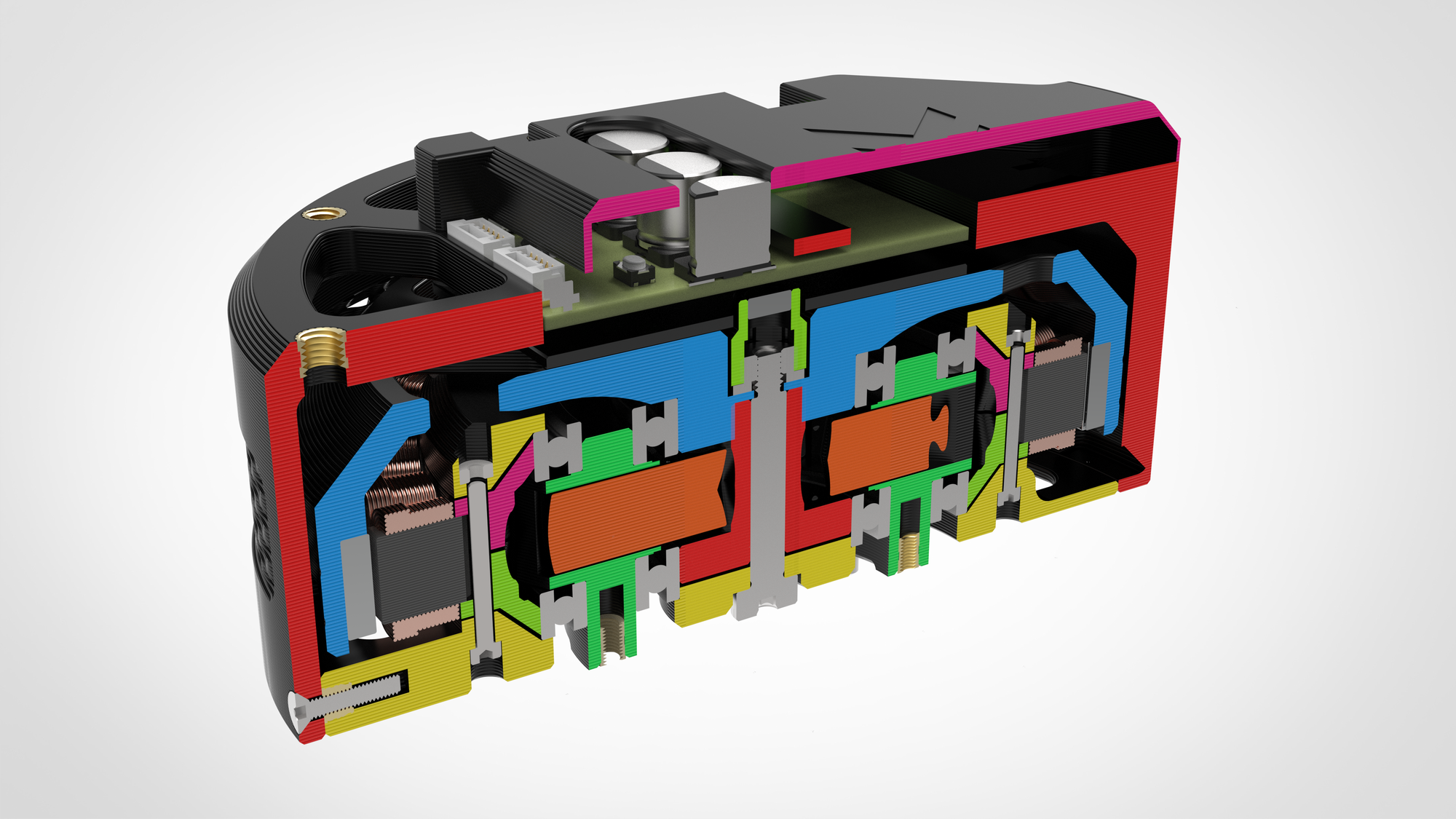
And here are the final bounding dimensions of the actuator.

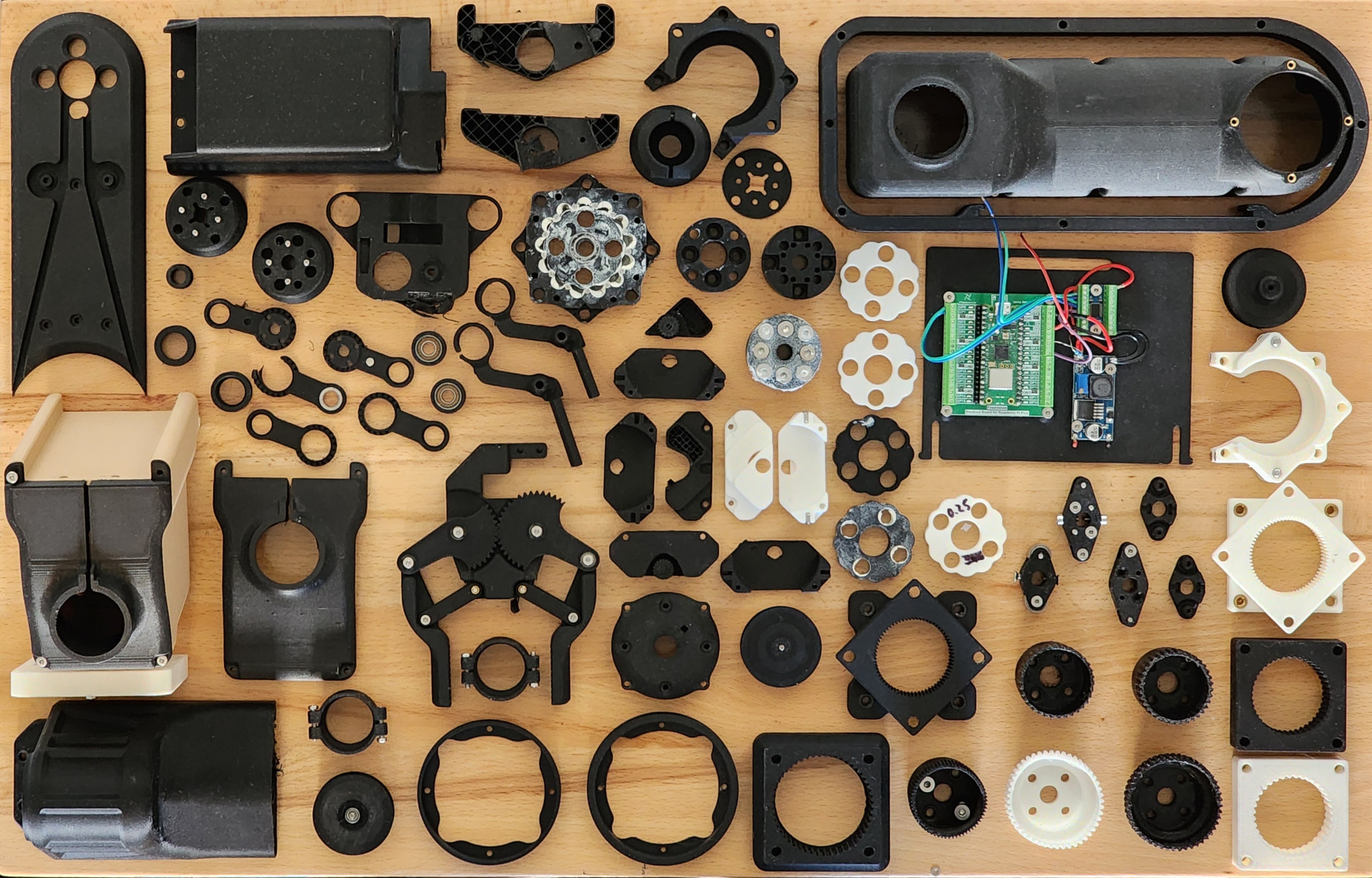
Fabrication and Assembly
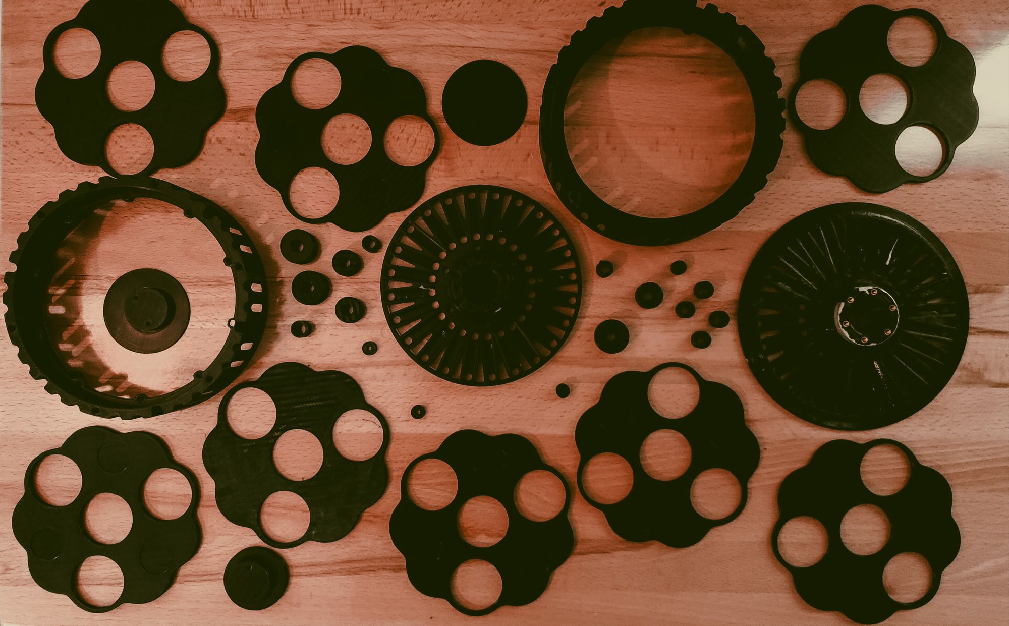
With all the custom parts on the actuator being 3D printed, most of the motor fabrication was just printing the components out. I printed all of the parts out of PA6-GF for some extra strength but I probably should have used just normal nylon filament for the gears if I had to do this again because the glass additive might cause abrasion over time.
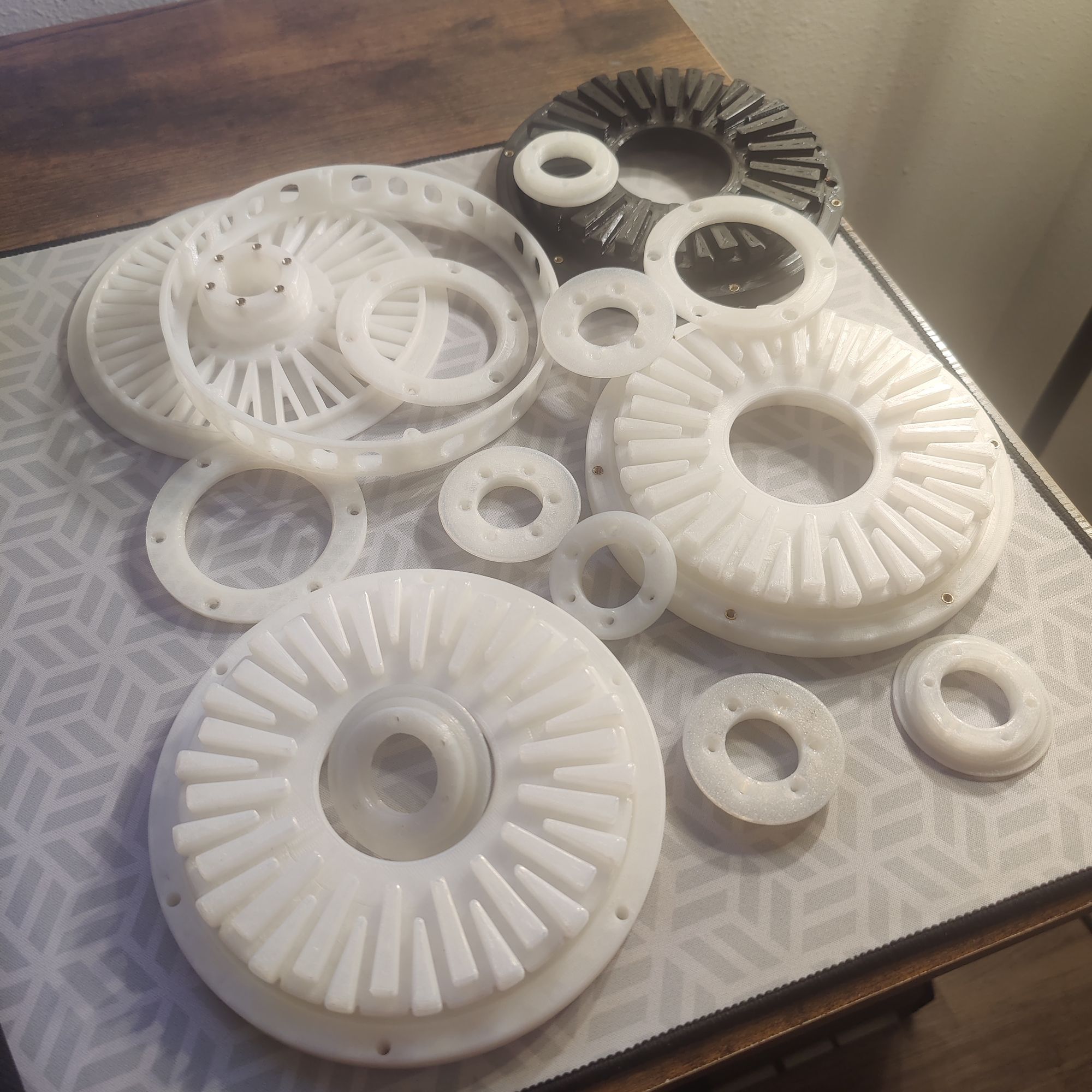
I did go through quite a few prototype parts making this though as I went through several different designs for nearly every part.
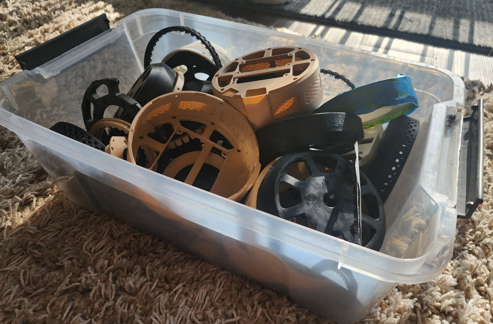
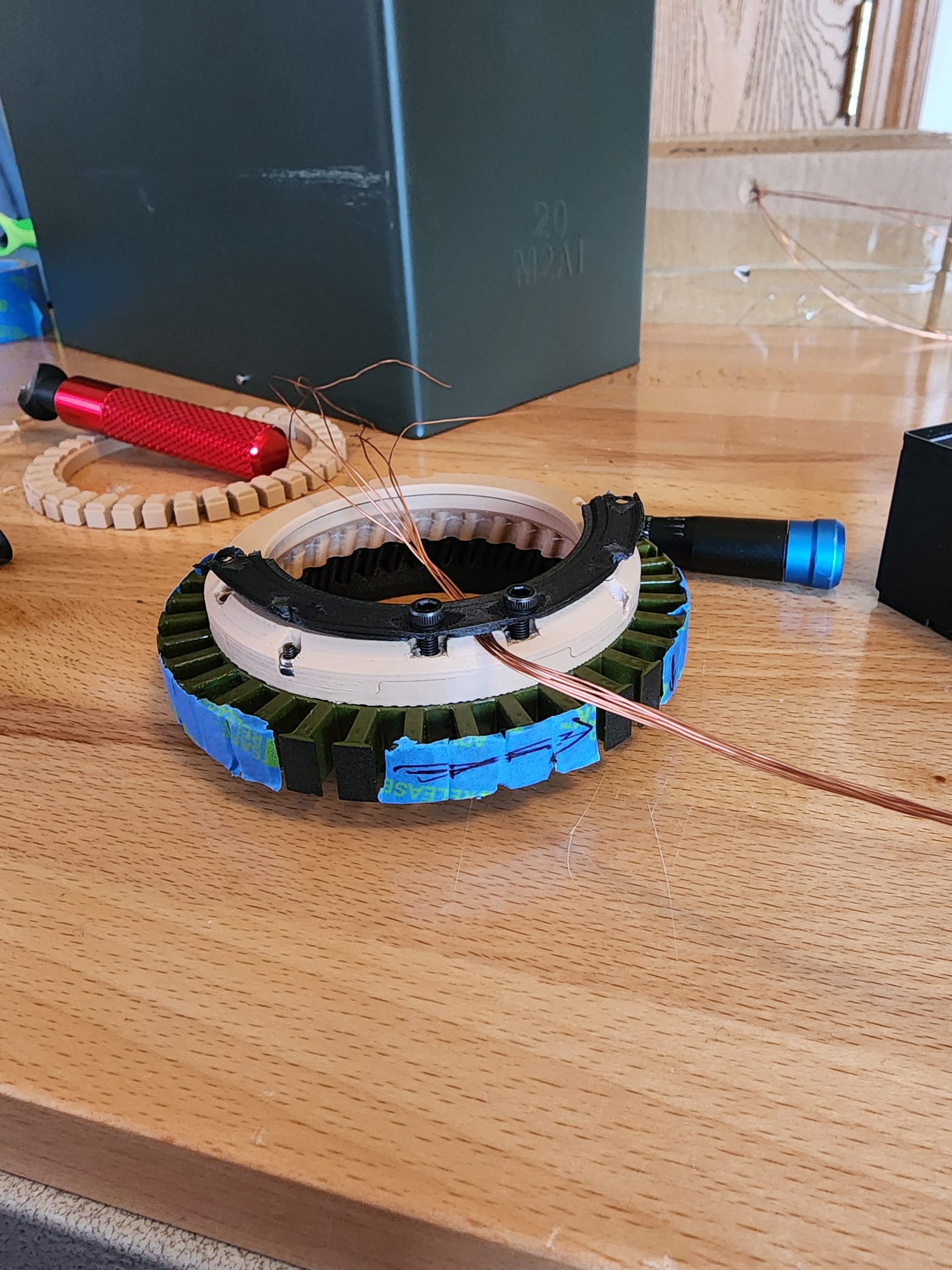
When assembling the rotor, I created a fixture to hold all my magnets at the desired air gap and then slid them in from the bottom. There are radial holes behind every magnet that I used to superglue them in place from behind after all the magnets were slid in place.
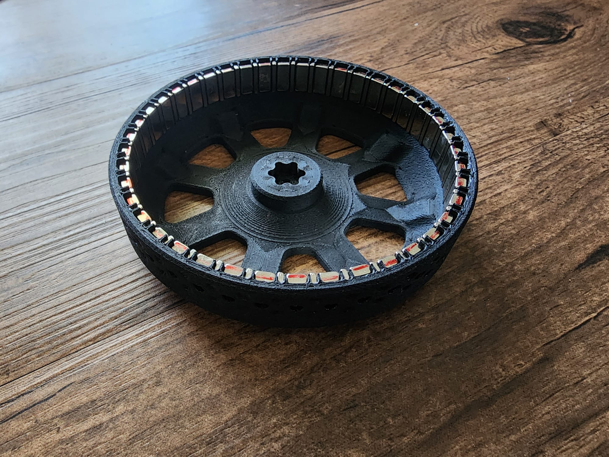

Finished rotor (left), Magnet insertion fixture (right)
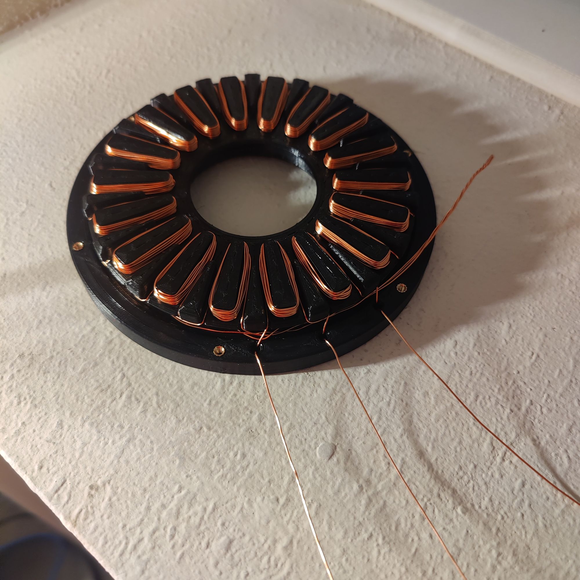
For the winding, it was a bit more complicated. I started by using the incredibly advanced tooling seen below to split 1 large spool into 6 smaller ones and then I fed all 6 through an equally sophisticated enclosure to get ready for winding.
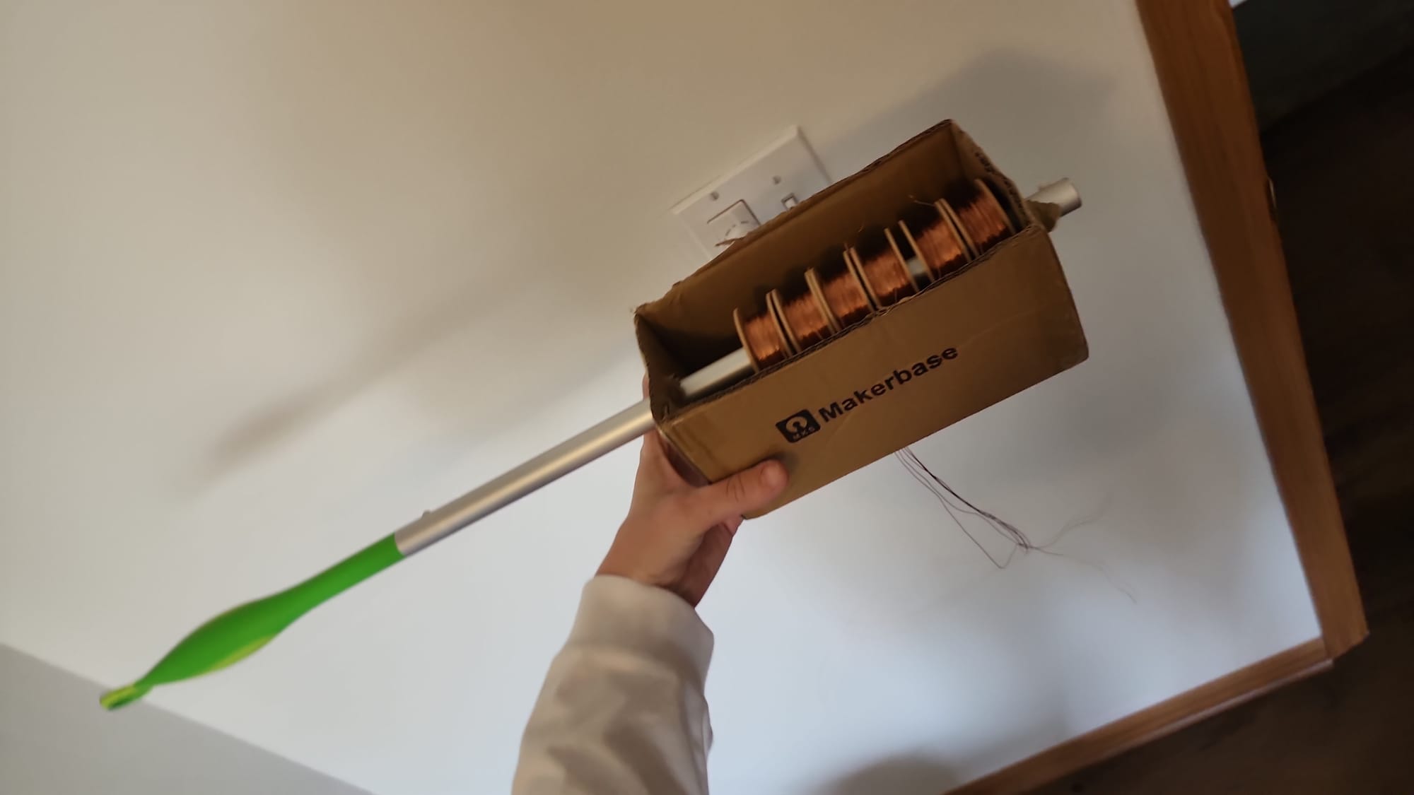
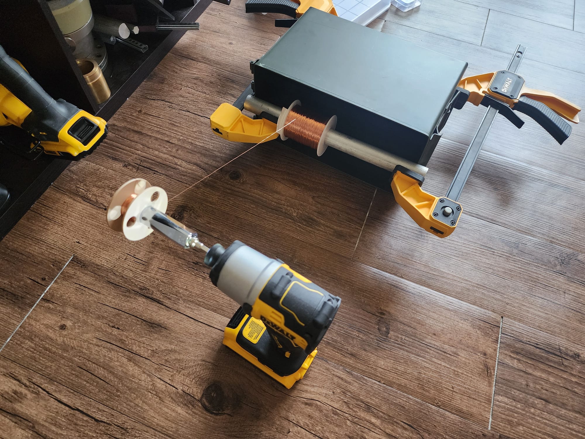
Photos for how I set up each individual copper spool and fed them all together to wind the stator
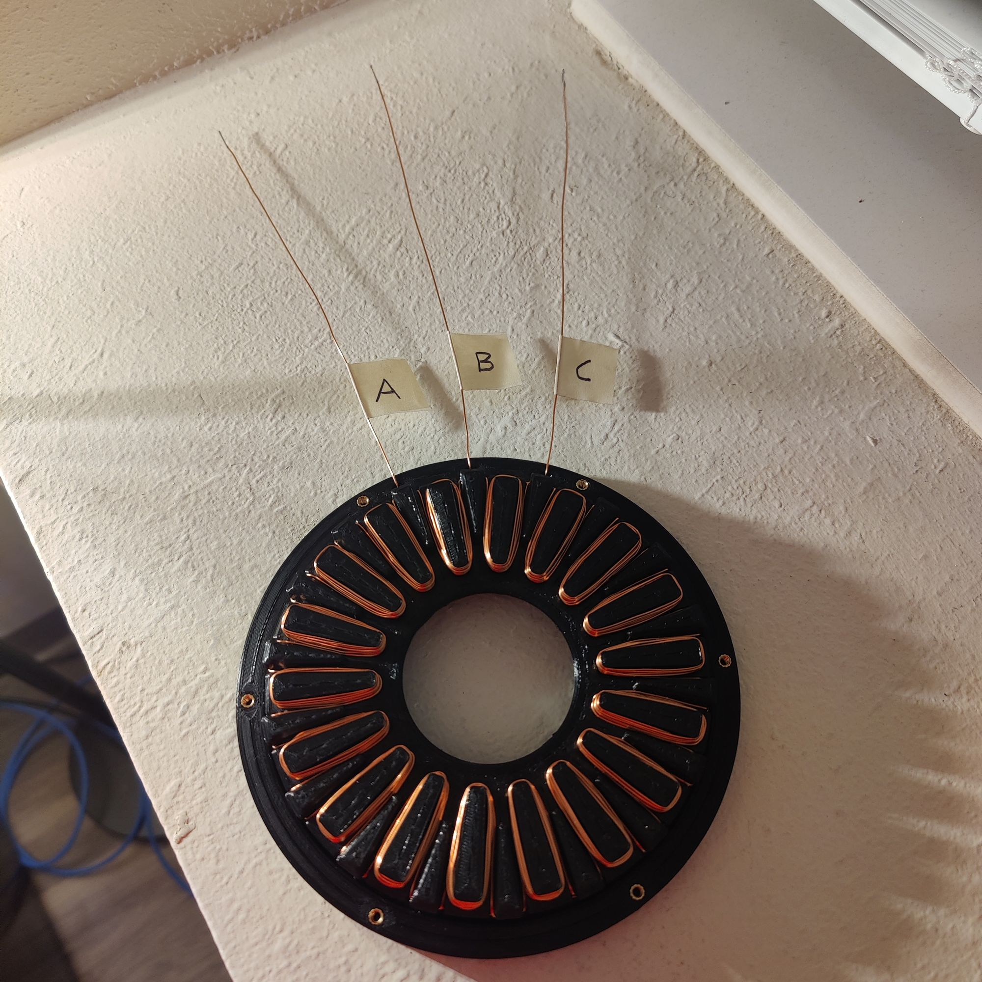
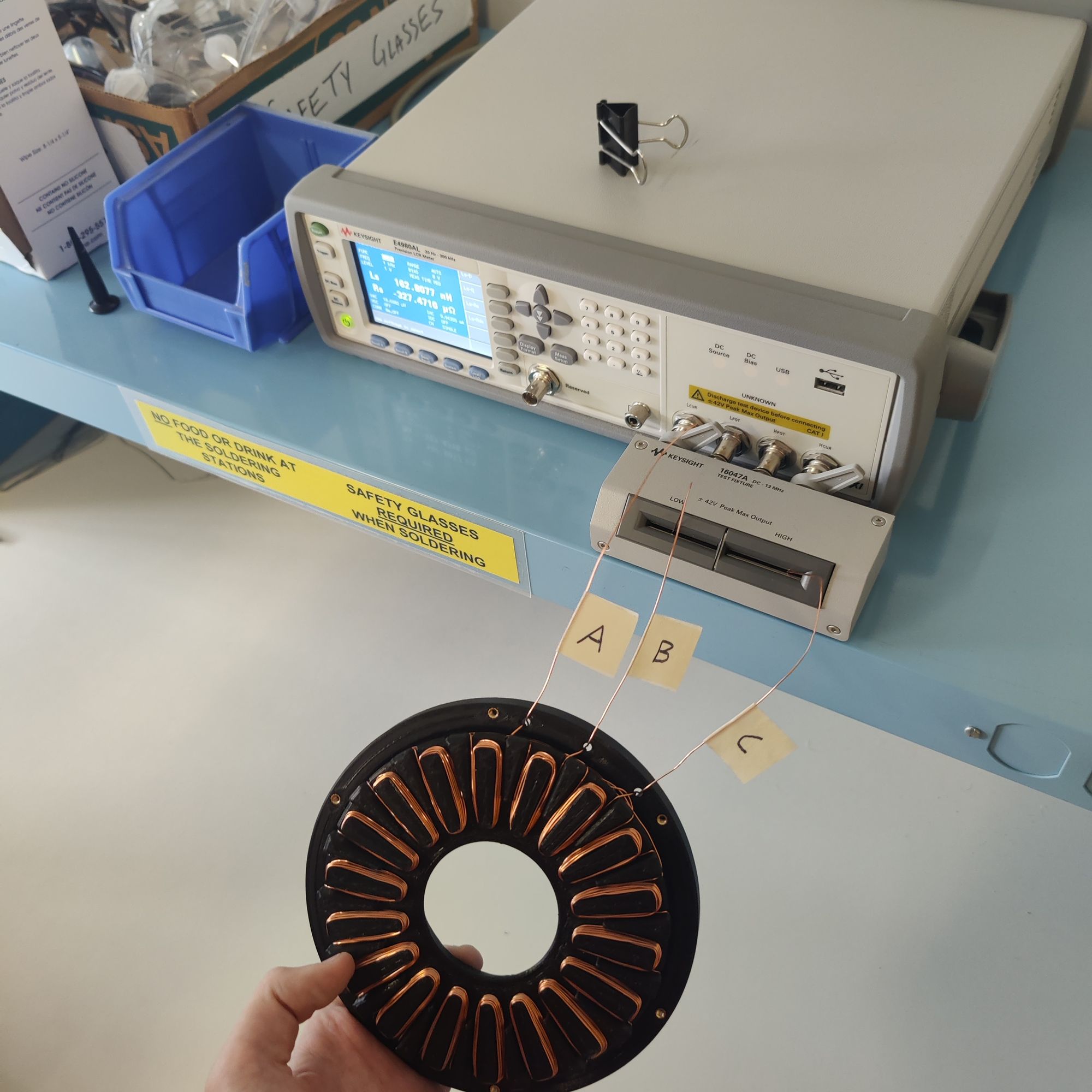
I then completed the arduous task of winding each phase, which in total took about 3 hours. After that, I took the wound stator to an LCR meter at my university in order to check the phase resistances and see if I had made any winding mistakes.
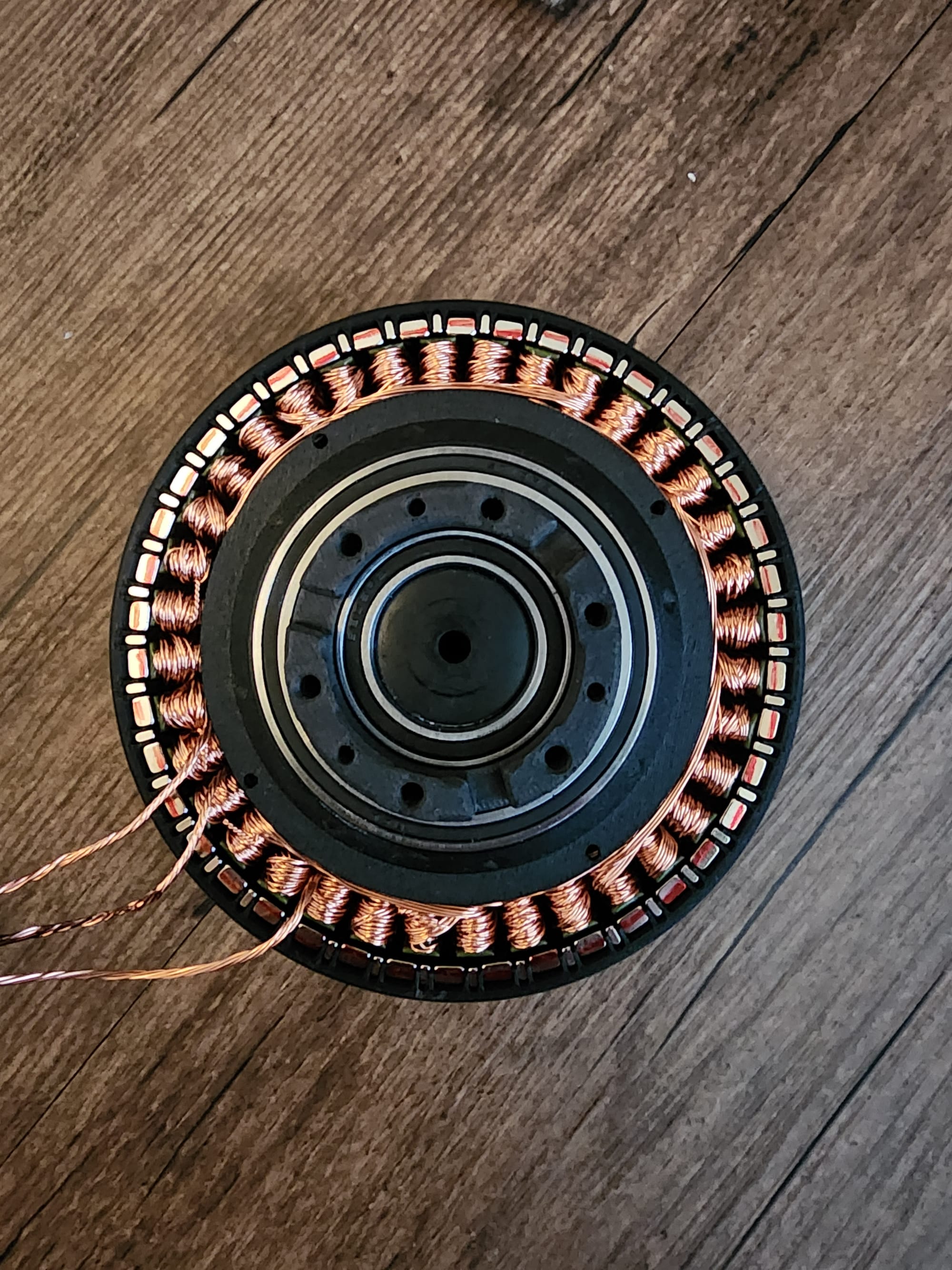
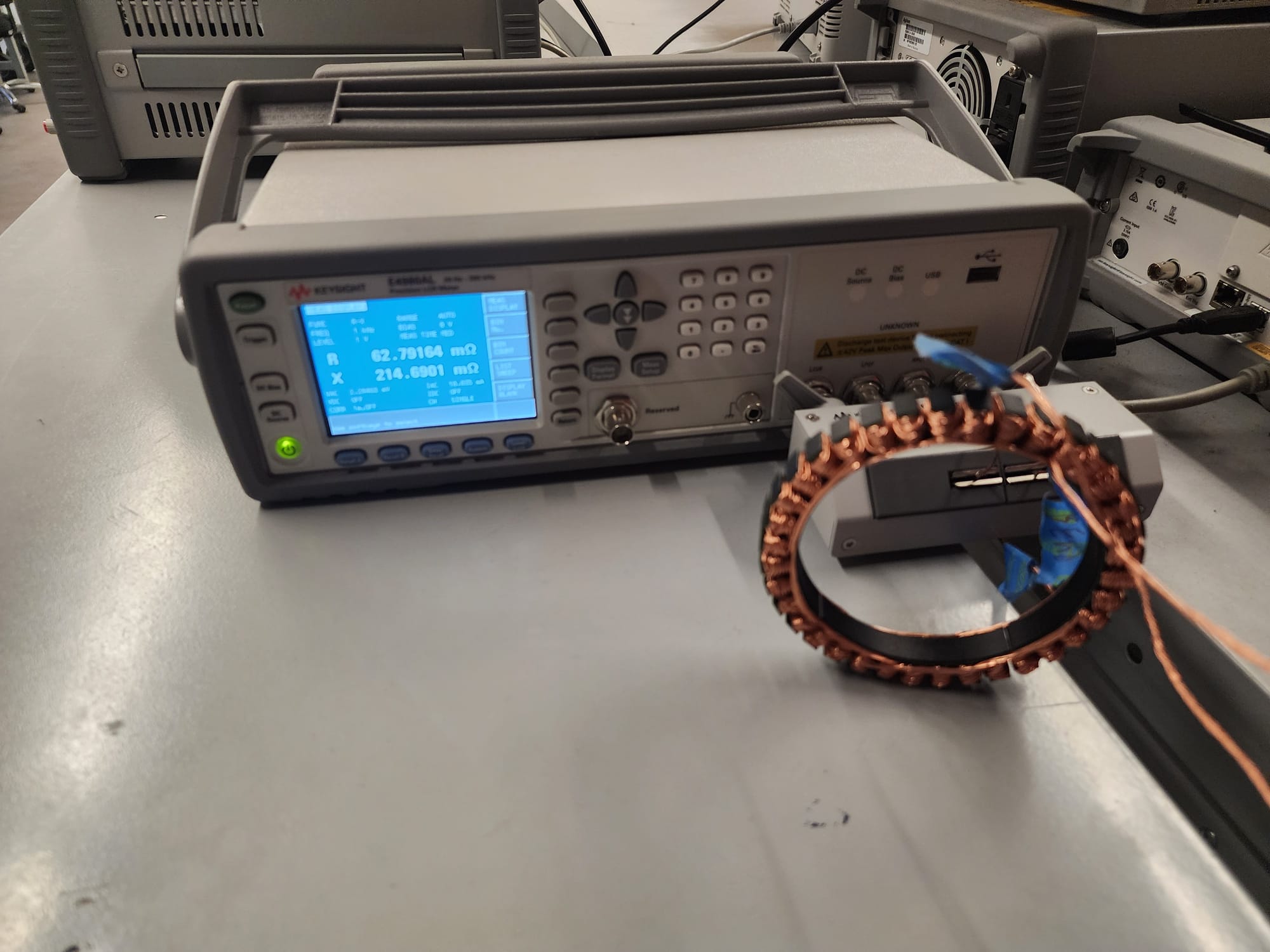

Finished wound stator as well as testing on the LCR meter
The results from the LCR meter are below. As you can see the tolerance between coils is incredibly good and far better than any of my other motors.
| Resistance (mΩ) | Impedance (μH) | |
|---|---|---|
| ɸA | 62.36 | 33.92 |
| ɸB | 62.42 | 33.04 |
| ɸC | 63.31 | 33.92 |
| Tolerance | ±0.76% | ±1.31% |
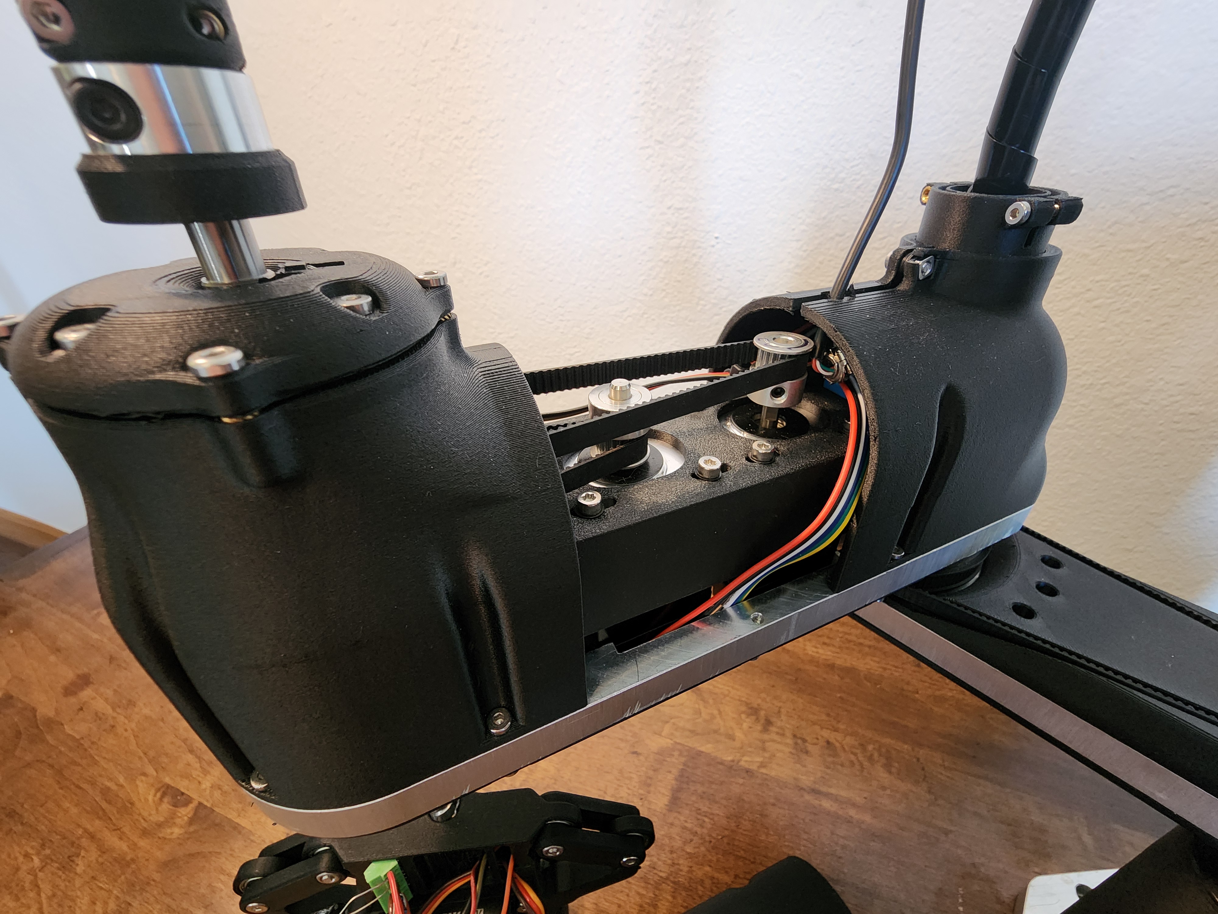
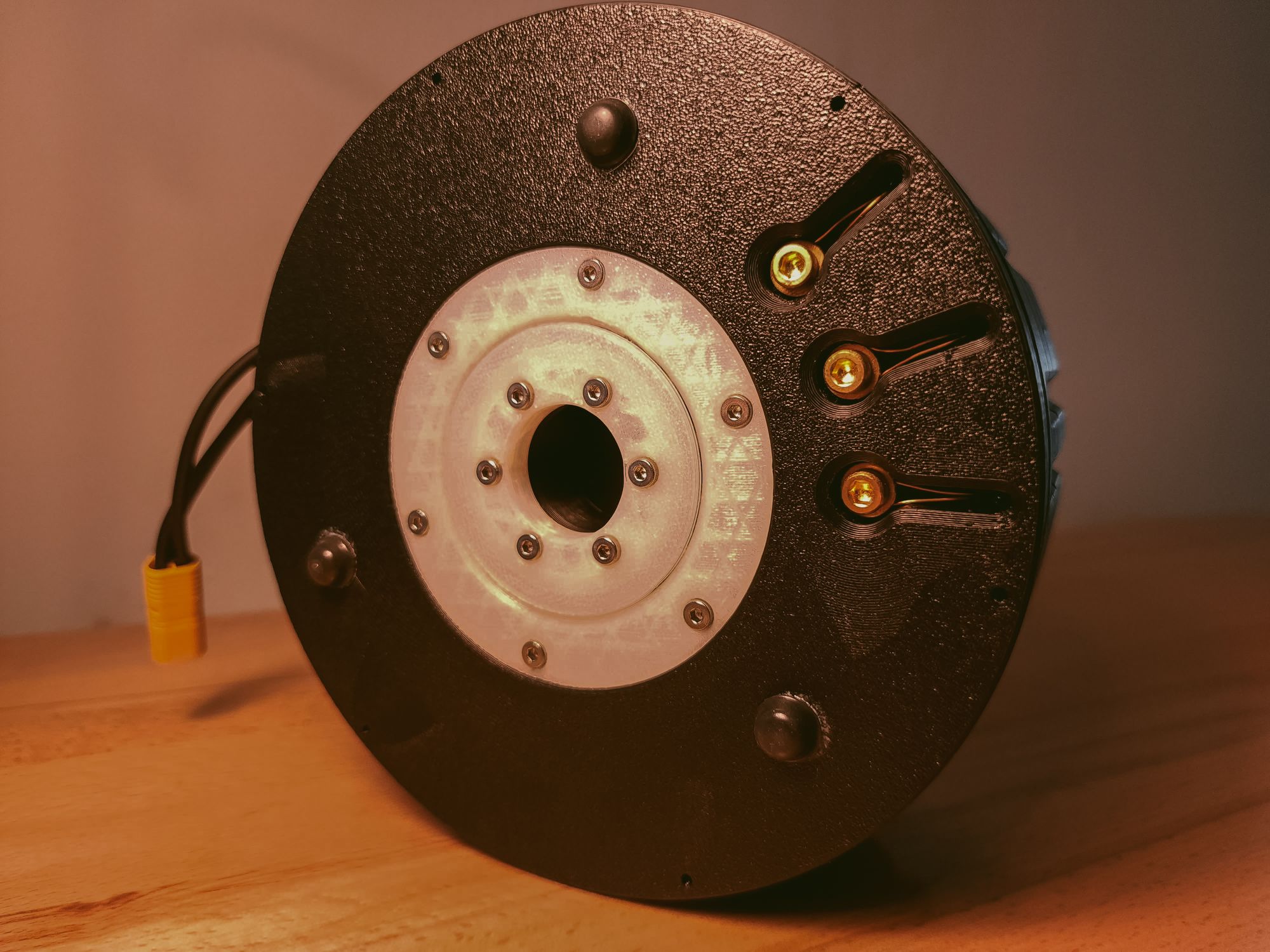
After assembling the gearbox with some lithium grease for lubrication I completed the assembly of the actuator.
Here is a video where you can see the gearbox working.
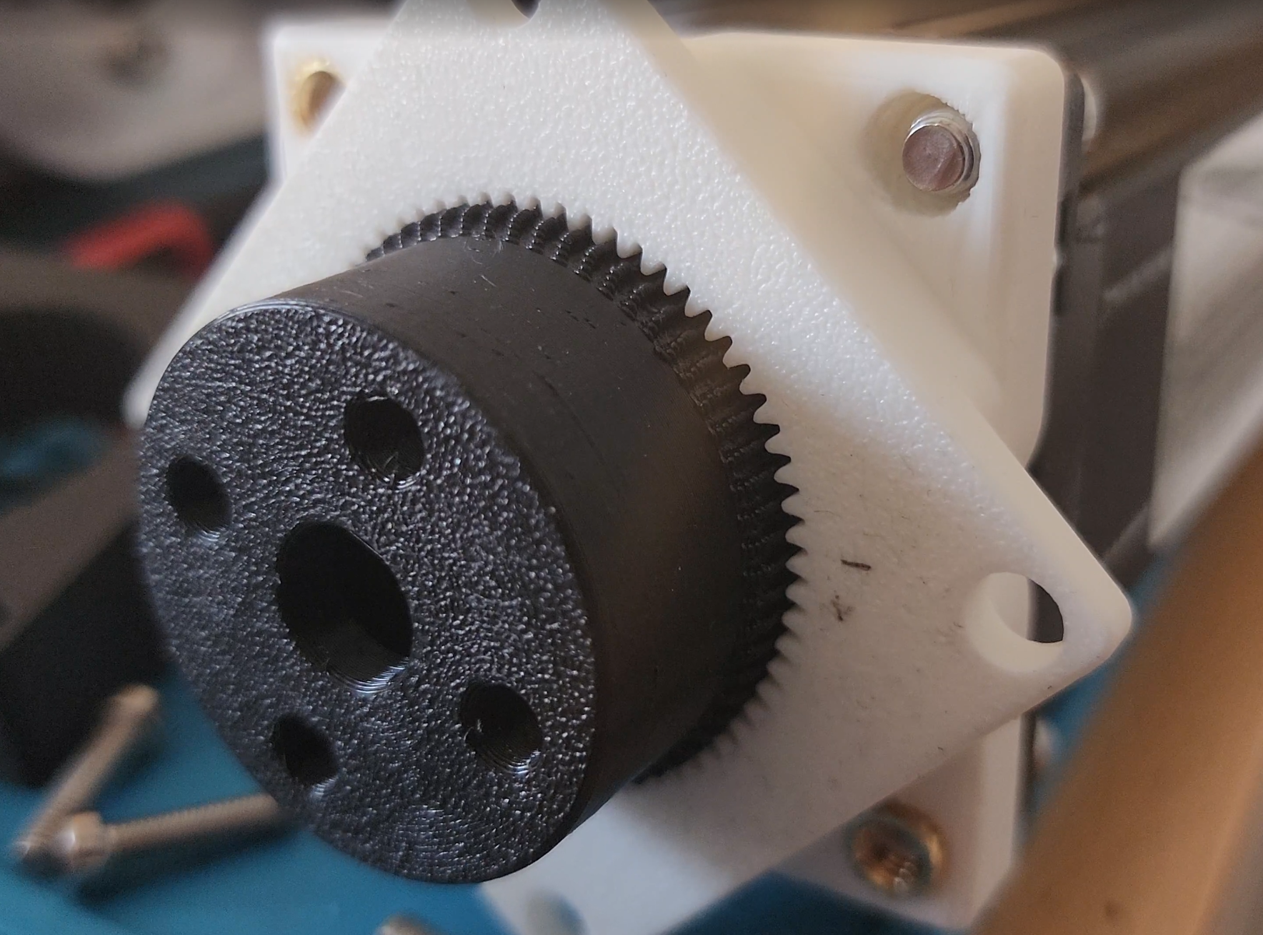
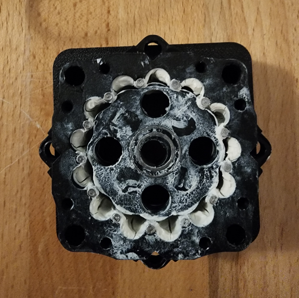
Final assembly (left), gearbox (right)
The final actuator has zero backlash, has little to no resistance when back-driven, and weighs in at 728 grams.
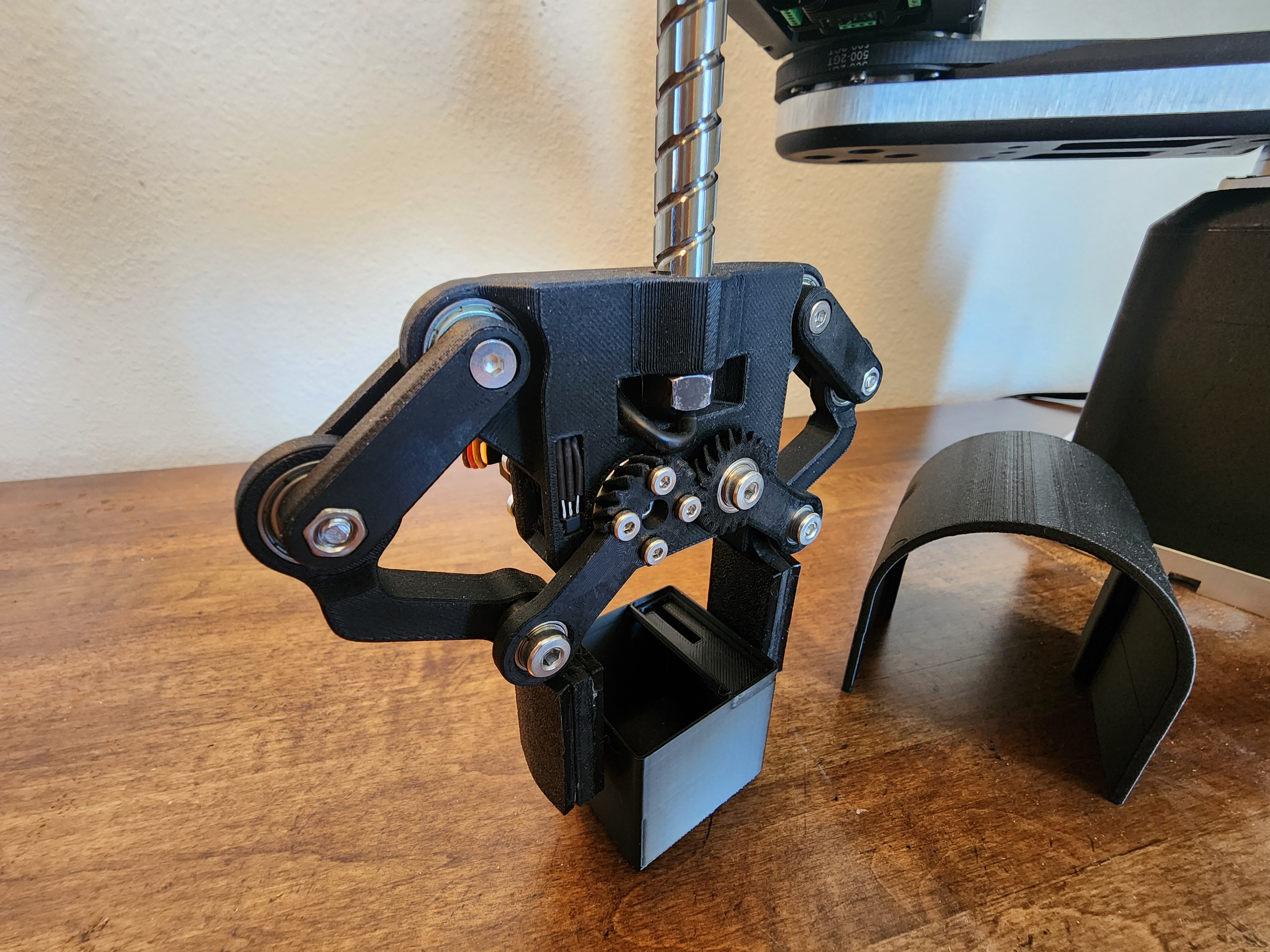
Testing
To start off testing this actuator I printed a 250mm arm that I could swing around and use to have a nice visual when calibrating the PID values for the FOC controller.
Here is a video of one of the first times I actually got it moving.
I also needed to figure out the torque constant and Kv for further tuning of the actuator. To do this, I backdrove the actuator with a power drill at a known RPM and measured the voltage generated from one of the phases.
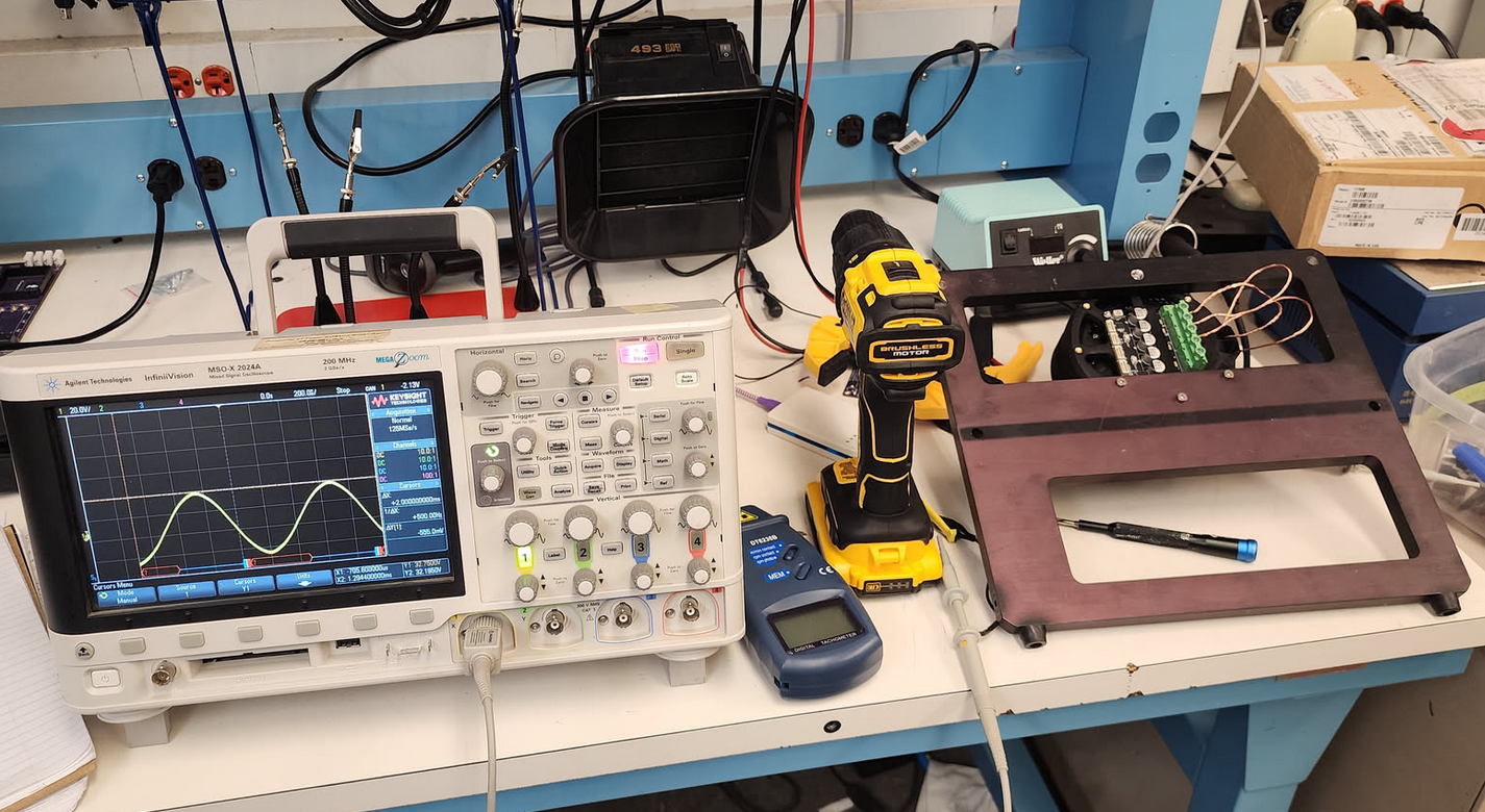
From this, I calculated that my actuator has a Kv of ~79, which lines up with what I would expect and allowed me to calculate the torque constant for the ODrive config.
After I got it nicely tuned, I set up my lab scale below the end of the arm and did a simple test to see what the holding torque would look like.
In this test the motor was able to hit a peak holding torque of 14Nm which was decently above my goal of 10. However, even with it outperforming it still looked like there was room to go further. The actuator only stopped because it had reached the current limit of my 24V 25A Meanwell power supply.
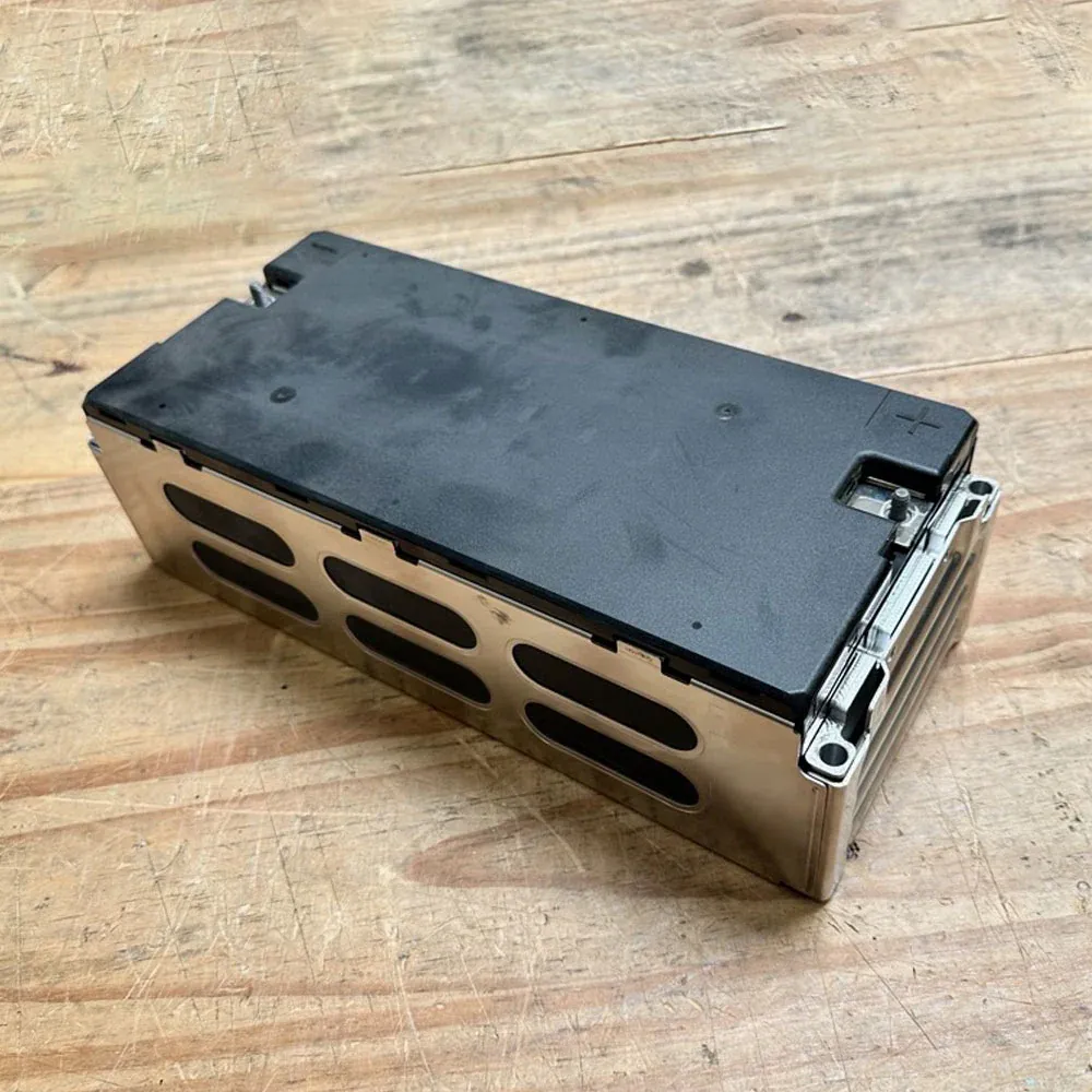
That meant I needed to find a DC power source that could push a lot of current. After asking around some forums for a power source people recommended for a project like this, I was pointed in the direction of reclaimed battery modules out of EVs. Luckily for me, after seeing my messages, Peter Holderith (@_baldtires) said that he had an extra module from an Audi E-tron that he didn't need and would send me for free.
This was extremely helpful and was the only way I would have been able to complete this project, so a big thanks to him. Check out his cool projects at the link above.
The module is able to be charged to 50V and has a maximum peak current output of 400A. 20kW of power was more than enough for what I would need during my next test, so I created a new setup powering the actuator off the Audi module.
For for this next, test the actuator had well exceeded the limits of my lab scale, so I hooked a string to a force gauge and pulled the actuator perpendicularly to the arm.

I also set up thermocouples inside the coils in order to see when I would be getting close to melting the insulation.
With this setup I was able to reach a maximum holding force of 117.5N which equates to a holding torque of 29.4Nm with the wires reaching a surface temperature of 78°C. Even in this test there was no mechanical or electrical failure and it only stopped because the controller had reached the 50A current limit I had set. However, I got the feeling that I was reaching the edge of what both the coils and plastic gearbox were capable of, so I left it at that. This gives the actuator a respectable torque to weight ratio of 40.38Nm/kg.
One crazy thing is that after a test of the actuator holding ~30Nm of torque for several minutes, there was still no perceptible backlash in the gearbox.
Cost Breakdown and Building Your Own
Of all the stuff I have created on this website I think this project is definitely something that people could benefit from and use in their own projects. This was the driving reason why I wanted to make this as low-cost as possible. The final bill of materials breakdown is below.
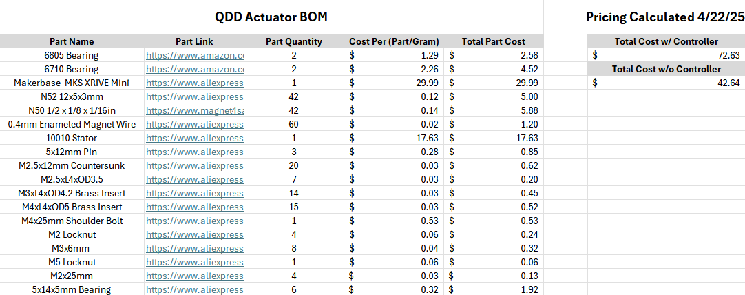
As you can see the final cost per actuator is just around $40 for the actuator and 70 if you include the controller.
This gives the actuator a cost to torque ratio of $2.47/Nm.
This is one of, if not the cheapest, actuator I have found online that has this level of performance.
All the motor CAD, FEMM simulations, BOM, and the ODrive config are open source and found via the link below. I only ask that If you use these files for your project that I be credited.

Conclusion
Out of all my projects this one was by far the one I had the most fun making. A lot of my other projects have mostly been useful for me to learn different things, but there wasn't much application in the final product. For this one however, I think I was able to implement some very novel ideas into a cost-effective end product that solves a real problem that I and hopefully others have. This project very much feels like the culmination of all my other motor projects, and I am really excited to see how people build off it!
]]>For the past year or so, I have been working on a SCARA robotic arm with the goal of replicating the mechanics and kinematics of commercial SCARA arms as closely as possible. This has been by far the most challenging project I have undertaken. This post provides an overview of the project, showing the design process from start to finish.
What's a SCARA arm?
SCARA (Selective Compliance Assembly Robot Arm) arms are traditionally used for pick-and-place operations. They have several advantages over traditional Cartesian arms, as they can generally be faster and maneuver into hard-to-reach areas.
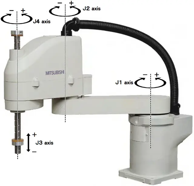
One aspect traditionally found on commercial SCARA arms is a ball spline screw. The ball spline screw allows the arm to have vertical Z movement and rotation around the same axis.
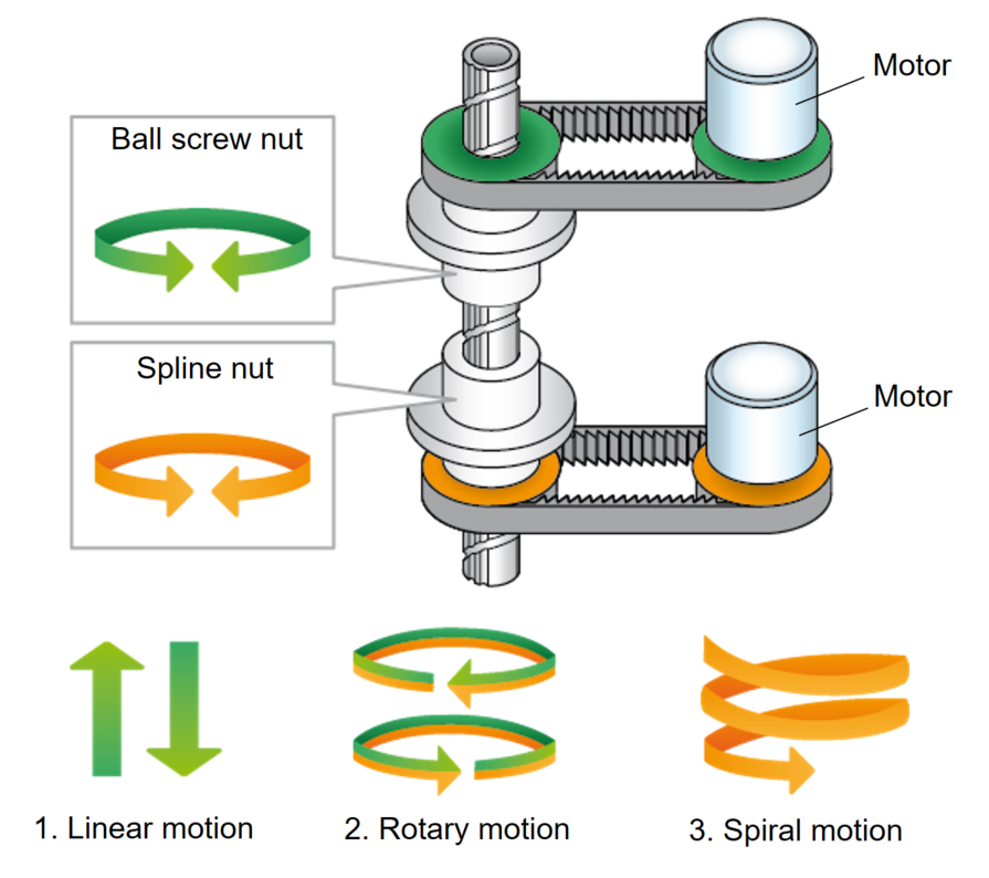
This was the main feature that drew me to the SCARA arm, as I thought the ball spline screw mechanism was extremely cool. I soon found out that SCARA arms seem to be the primary application for ball spline screws, so the ones available online are often made for specific SCARA models. They are generally extremely expensive due to low demand and being hard-to-manufacture parts. Every DIY SCARA arm design I found online instead places the Z-axis at the base of the robot, which was a compromise I did not want to make.
After a few weeks of setting up some eBay alerts, I found a listing from someone selling a ball spline screw that they supposedly found at a garage sale. $80 later, I had this part that came with no documentation or CAD models.
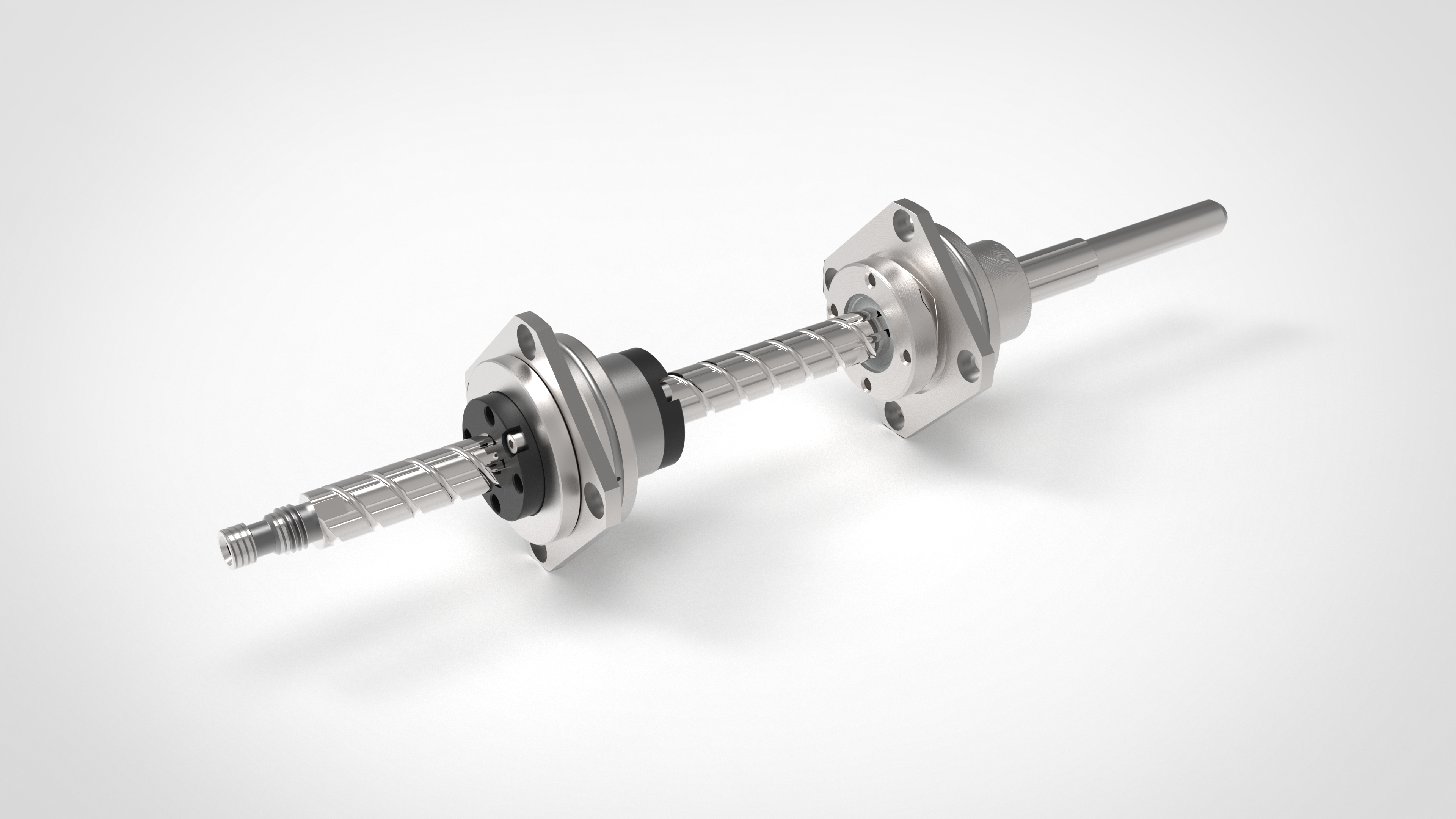
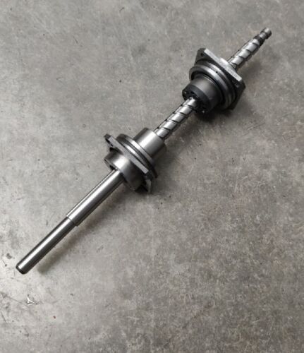
Photo of the ball spline screw along with the CAD model I made of it
Project Requirements
Now that I had a part to design a robot around, I created some design requirements for the project:
- Prioritize precision and repeatability over speed
- Machined arm components to improve rigidity and strength
- End effector needs to be able to rotate continuously
- All power and electronics contained within the main body
- Try to make the mechanical/aesthetic design similar to commercially available SCARA robots
The Mechanical Design
Motors and Gearboxes
The motors and gearboxes were by far the hardest part of this project for me. I chose to use two NEMA 23 closed-loop stepper motors for the two main arms and two NEMA 17 closed-loop stepper motors for the Z-axis and rotation.
Given that each arm of the SCARA is 180mm, any backlash in the joints will grow quite significantly over the length of the arm. So, when it came to choosing a reducer for the motors, minimizing backlash was the main priority.
Against my better judgment, I initially chose to try direct drive, as that would have no backlash at all, but it proved to have far too little torque to successfully do anything.
When creating a reducer, I originally chose to try to make a 3D-printed harmonic drive.
Render and image of harmonic drive prototype
After several revisions, I arrived at the design above, but unfortunately, in all the testing I did, I could not get the backlash below 2-3 degrees. I think that when making a harmonic gearbox this small and from plastic, the teeth are just not strong enough to counteract the torque from the arm.
After this failure, I moved on to designing a cycloidal drive, which is something I had a bit of experience with from a past cycloidal gearbox project. After probably a dozen revisions, this was the design I landed on.
Render and image of cycloidal drive prototype
During initial testing, this seemed promising, as I couldn't feel any backlash whatsoever. Unfortunately, after stress testing the gearbox, the outer pins started to deform the cycloid, which introduced around 2-3 degrees of backlash. If I had been able to machine the cycloids, this design might have worked.
The Belt Drive Gearbox
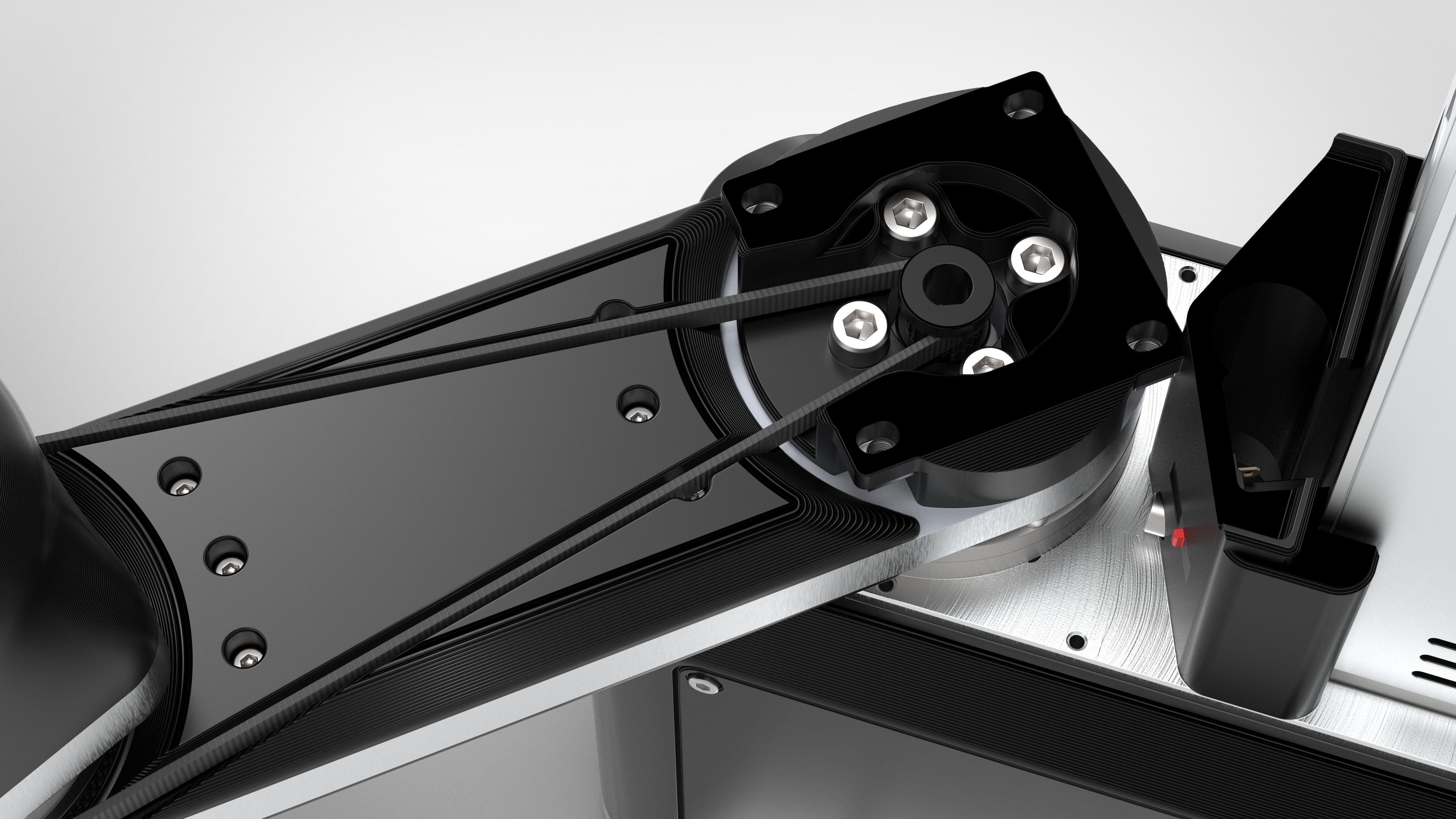
After some frustration figuring out the gearbox situation, I chose to try to make a belt drive gearbox. This design combines two 3:1 belt reductions for an overall 9:1 reduction. The gearbox uses jack screws to tension the belts and keep the backlash to a minimum.
Renders of belt drive gearbox
Here is a short video of an initial test I did of this gearbox.
When testing this on the robotic arm, I measured ~25-30 arcminutes of backlash. While not perfect, compared to my other designs and considering the compact form factor, I was really impressed by the results. For reference, this planetary gearbox advertises 30 arcminutes of backlash but is 71.5 mm tall, while my gearbox is only 22 mm tall.
One downside is that because the parts are plastic and use jack screws for tensioning, material creep over time can cause the backlash to increase, even when the robot is sitting idle. Through my testing, I found that this does not seem to have much of an effect yet, but if it does down the line, the jack screws are easily accessible to re-tension the belts.
Elbow Motor Reduction
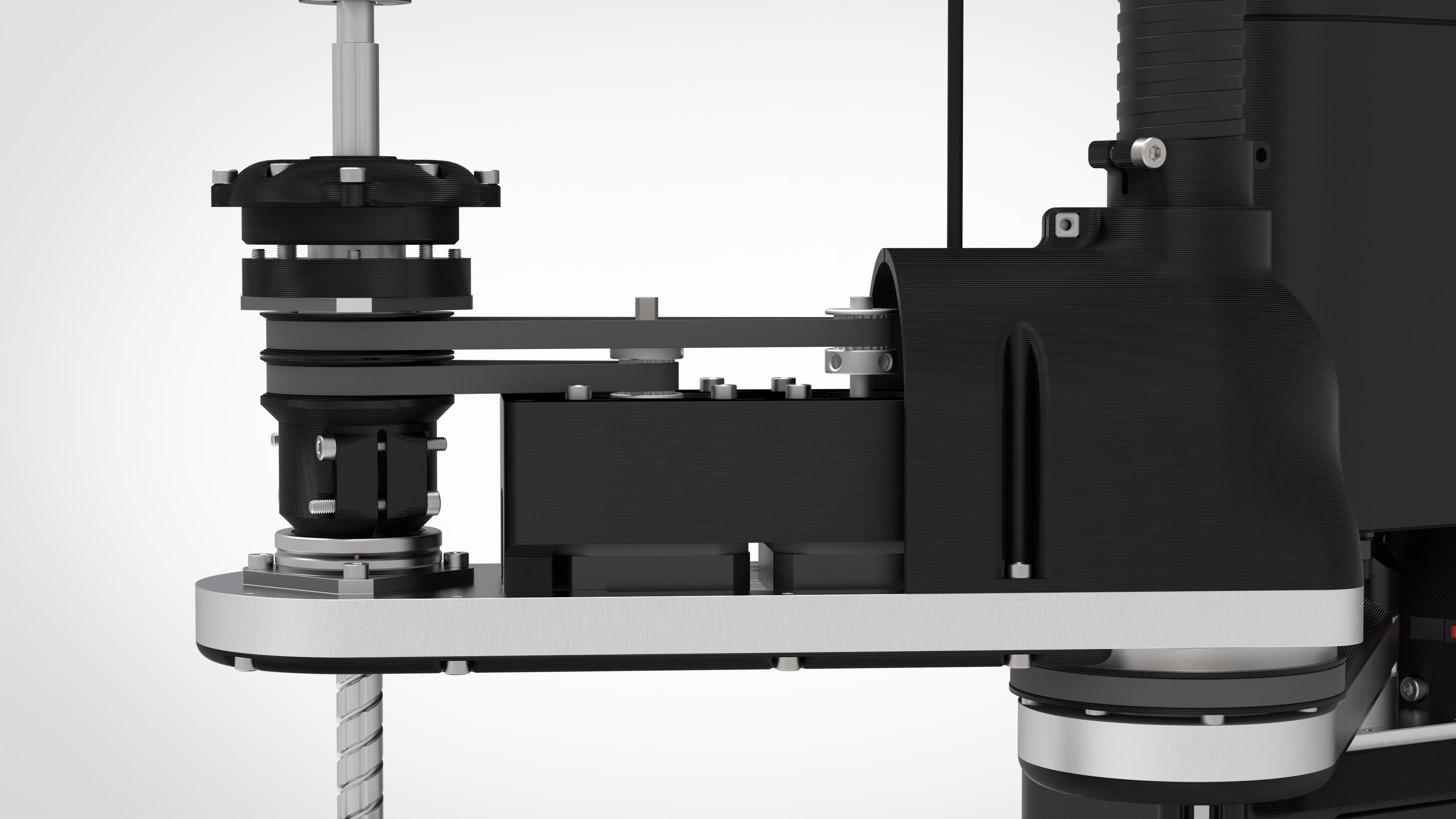
For the reduction of the elbow motor, I chose to integrate a belt reduction over the length of the shoulder linkage, giving that joint a 6:1 reduction.
This belt is tensioned simply by tightening the motor down inside its slotted mounting holes while holding the belt under tension.
Z and Rotation Motors
The Z and rotation motors also use the same slot tensioning technique, using belts with a 3:1 reduction to interface with both ends of the ball spline screw.
Servo Gripper
For the end effector of the arm, I chose to design a simple four-bar linkage gripper using helical gears.
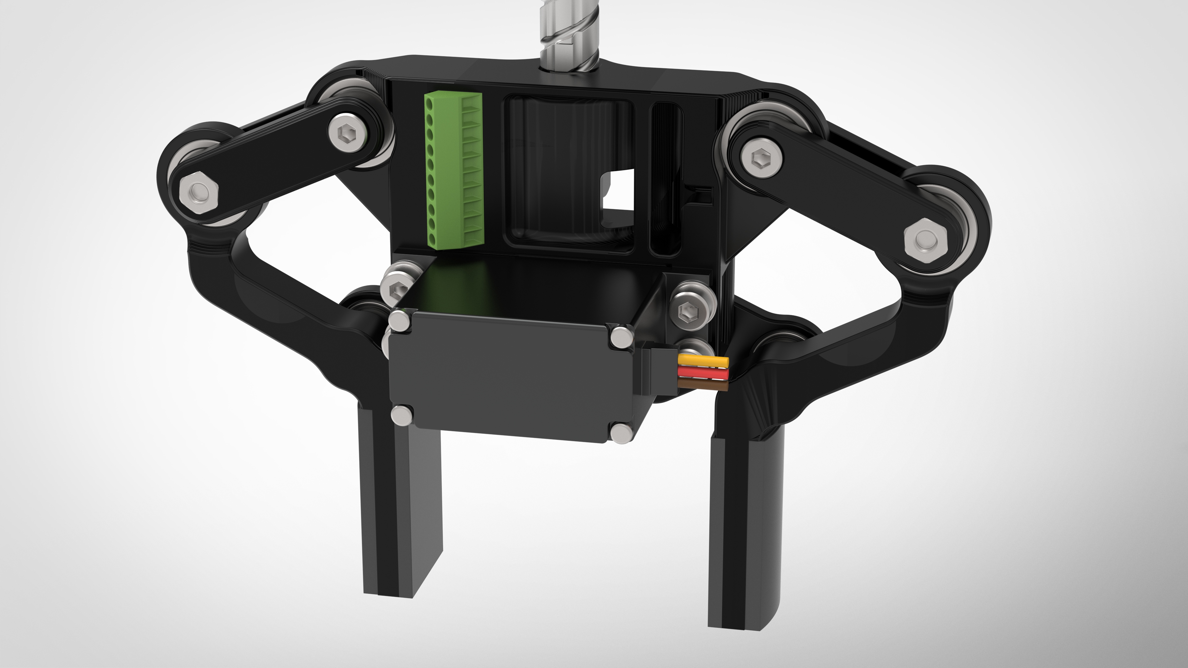
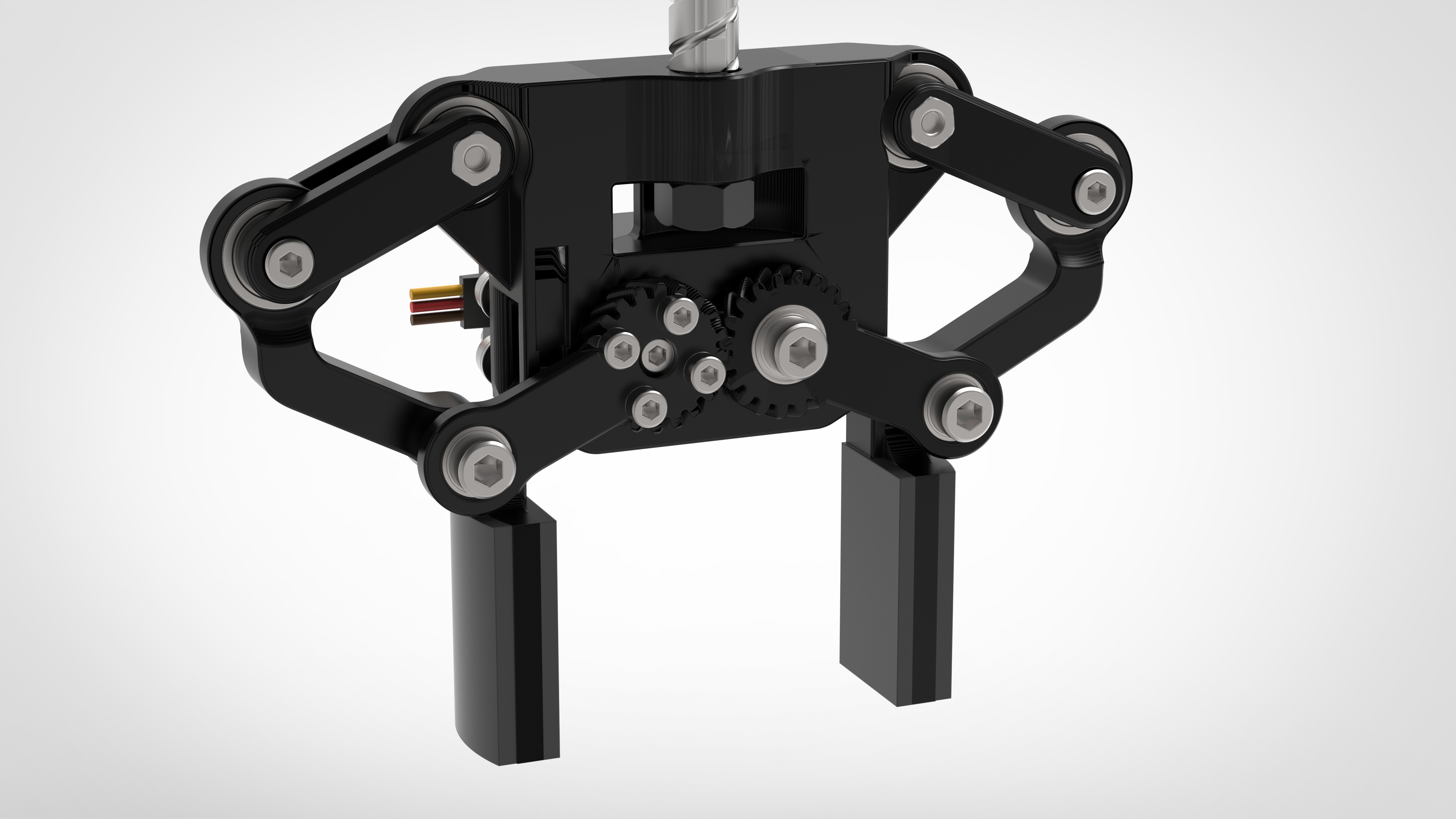
Renders of servo gripper
One difficult aspect of this was providing power and communication through a shaft that could theoretically spin indefinitely.
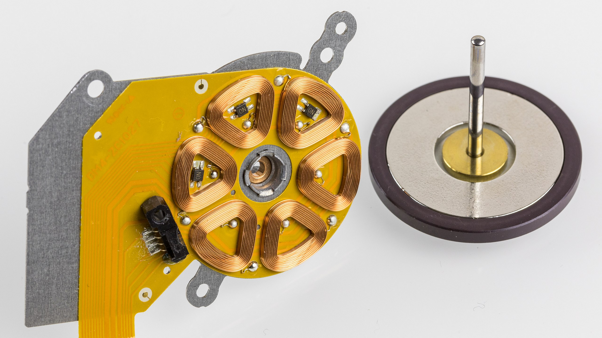
The obvious answer is to use a slip ring, but I struggled to find one that could handle the current and have a small enough form factor to fit. I solved this by using a magnetic concentric 4-pin connector that uses pogo pins to make electrical contact.
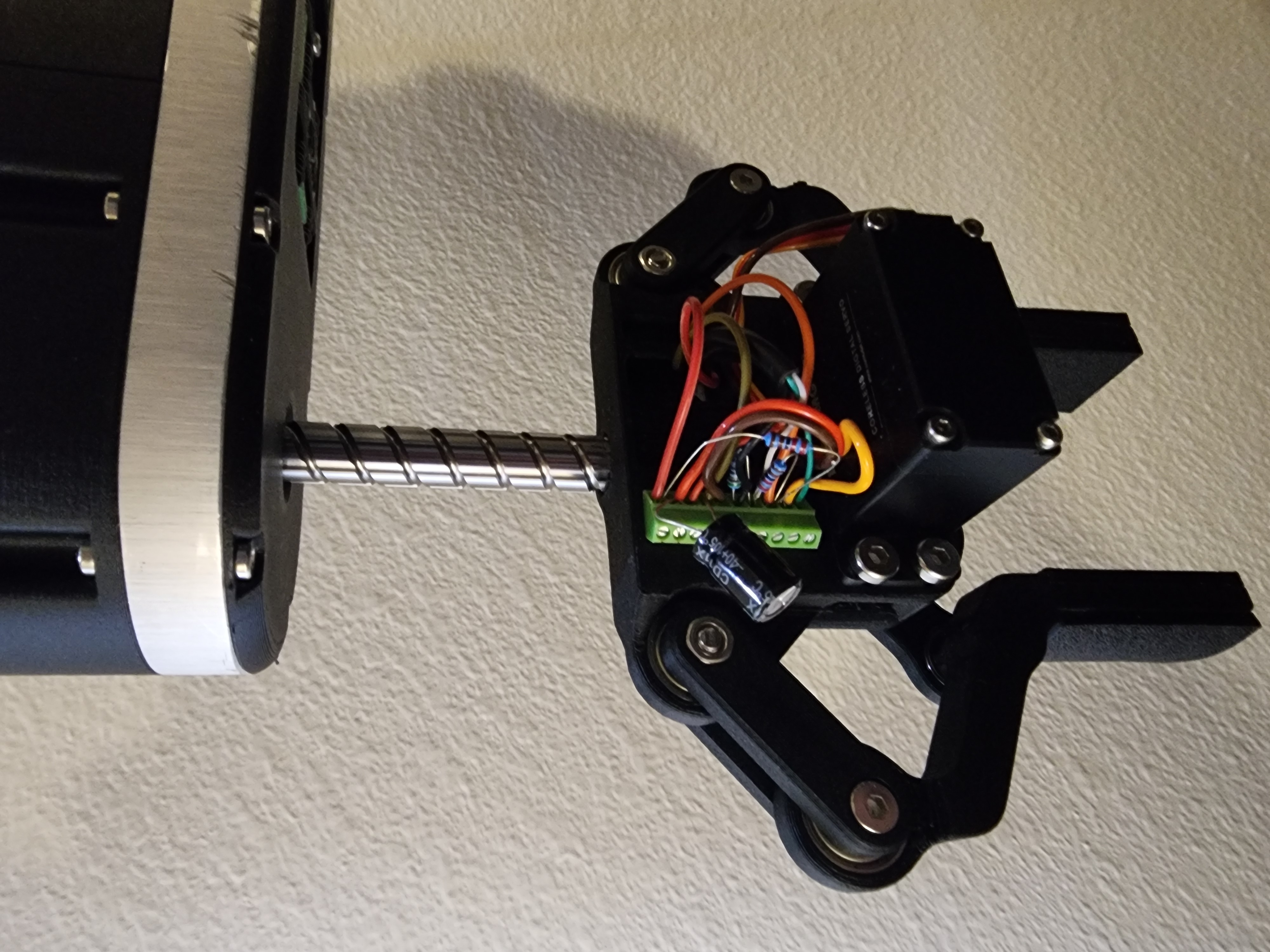
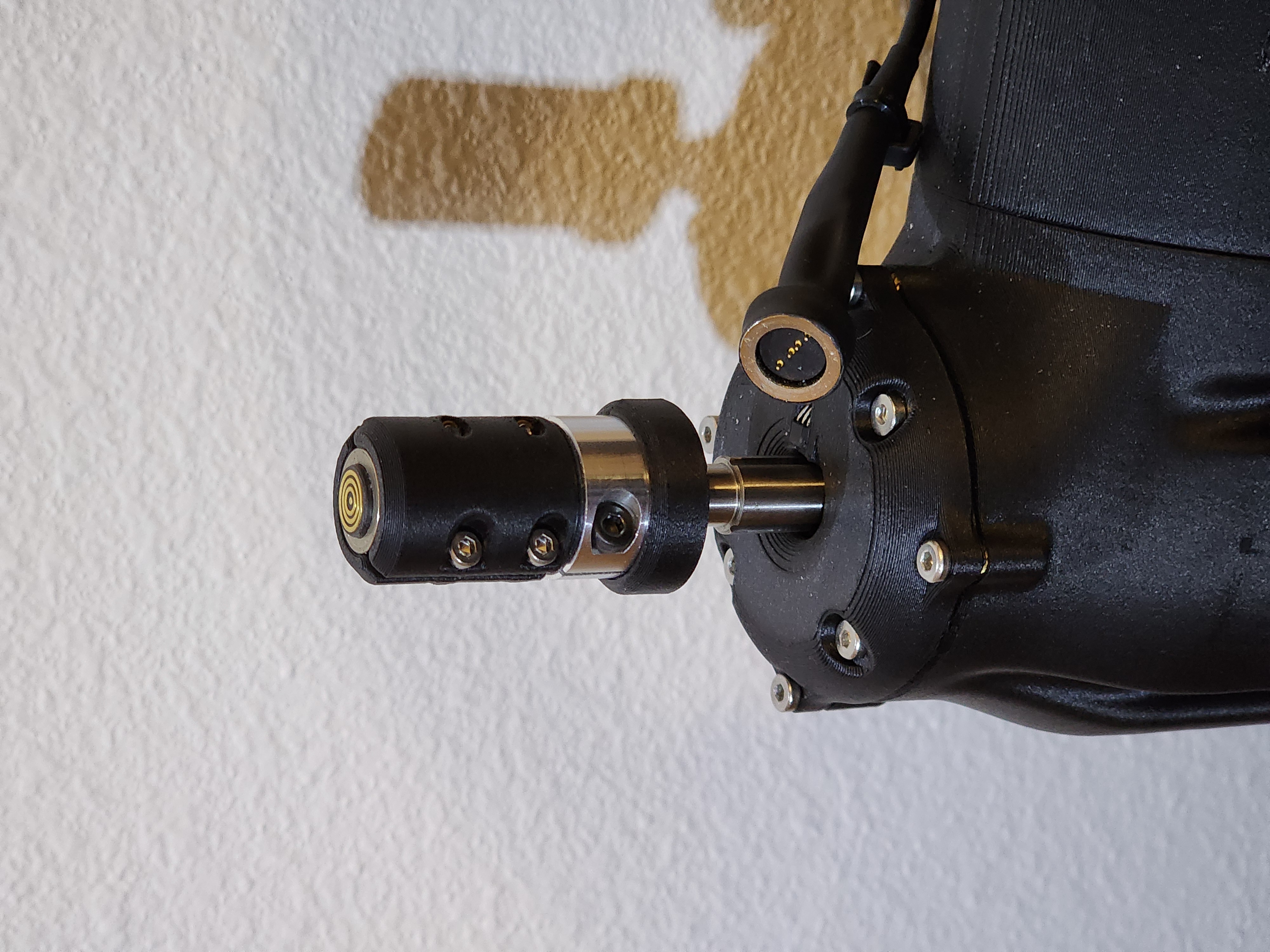
Output wiring to gripper (left), 4 pin magnetic connector (right)
In the right photo, you can also just barely see the Hall effect sensor that is used to home the Z and rotation axes.
The Final Mechanical Design
Putting all of this together, this is the final design of the arm that you can see in the draggable view below.
Software
For the software side of things, I decided to base the arm on the Arduino Uno R4 Wifi because it has a 32-bit chip and 5V I/O, which is needed for the stepper motors (and I didn't want to bother with level shifters).
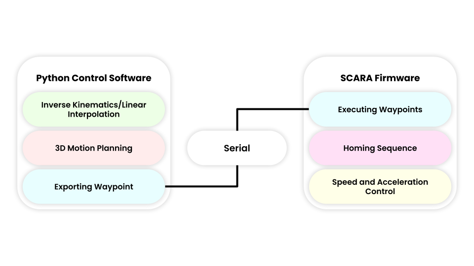
The software for the arm is split between a controller app that handles all the inverse kinematics and interpolation, and the low-level firmware that takes the calculated waypoints from the control software and executes them.
Inverse Kinematics
A core part of robotics is inverse kinematics. If I have an $(x,y)$ coordinate I want the arm to travel to, I can use the equations below to find the angles the motors need to be at to reach that point.
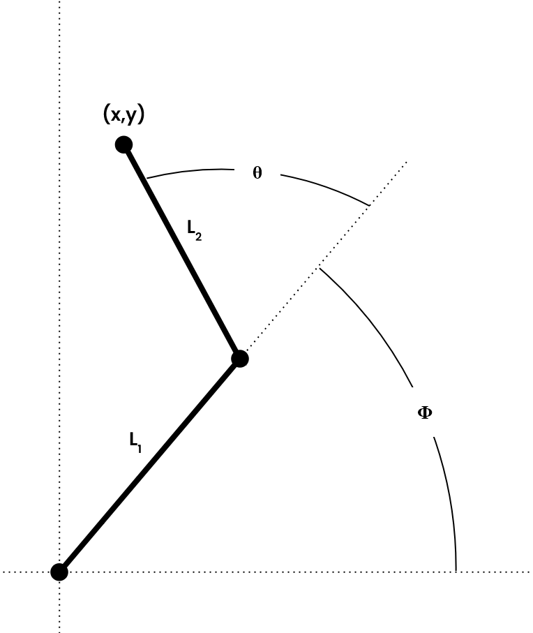
$$\theta_1 = \arccos\left(\frac{x^2 + y^2 - L_1^2 - L_2^2}{2L_1L_2}\right)$$
$$\theta_2 = -\theta_1$$
$$ \phi_1 = \text{atan2} \begin{pmatrix} L_2S_2x + (L_1 + L_2C_2)y \\ (L_1 + L_2C_2)x - L_2S_2y \end{pmatrix} $$
$$\phi_2 = -\phi_1 + 2\text{atan2}(x,y)$$
$$S_2 = \sqrt{1-C_2^2}$$
$$C_2 = \frac{x^2 + y^2 - L_1^2 - L_2^2}{2L_1L_2}$$
The $\theta_1$ and $\phi_1$ would be the values for the "left hand" solution and $\theta_2$ and $\phi_2$ would be used for the "right hand" solution. I chose to write my code so that if both right and left hand solutions are valid, it chooses the pair of angles that have the least angular distance to the next waypoint.
Control Software
To be perfectly honest, the control software got a bit carried away, and I probably should have used something like MoveIt with ROS2 instead of doing everything from scratch. However, for the most part, I enjoyed the process and feel like I learned a lot more doing it this way.
Here is a screenshot and video of the control software.
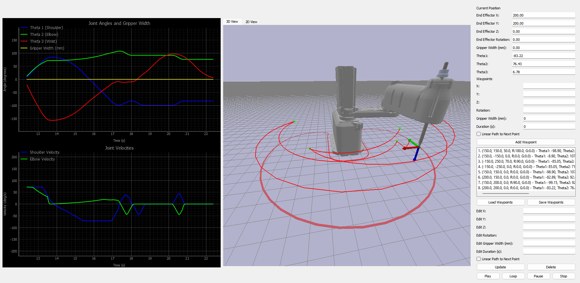
Firmware
I won't delve too in-depth on the firmware because, to be honest, it's hard to visualize and kind of boring. I chose to use the AccelStepper/MultiStepper library to control the steppers, which ironically doesn't support acceleration when commanding multiple motors to reach a target simultaneously.
I created my own replacement for the MultiStepper library. With it, I can command the robot to move to a waypoint, and it will vary the velocities of all motors so they reach the intended target simultaneously, including acceleration. This lessens the change in momentum when moving from point to point, allowing the robot to reach higher speeds.
If anyone is interested in looking through the code for the control software or the firmware, it's available on my GitHub.
 CKraft11
Manufacturing
While most of the arm consists of 3D-printed parts, the four aluminum plates that make up the arm required a bit more work.
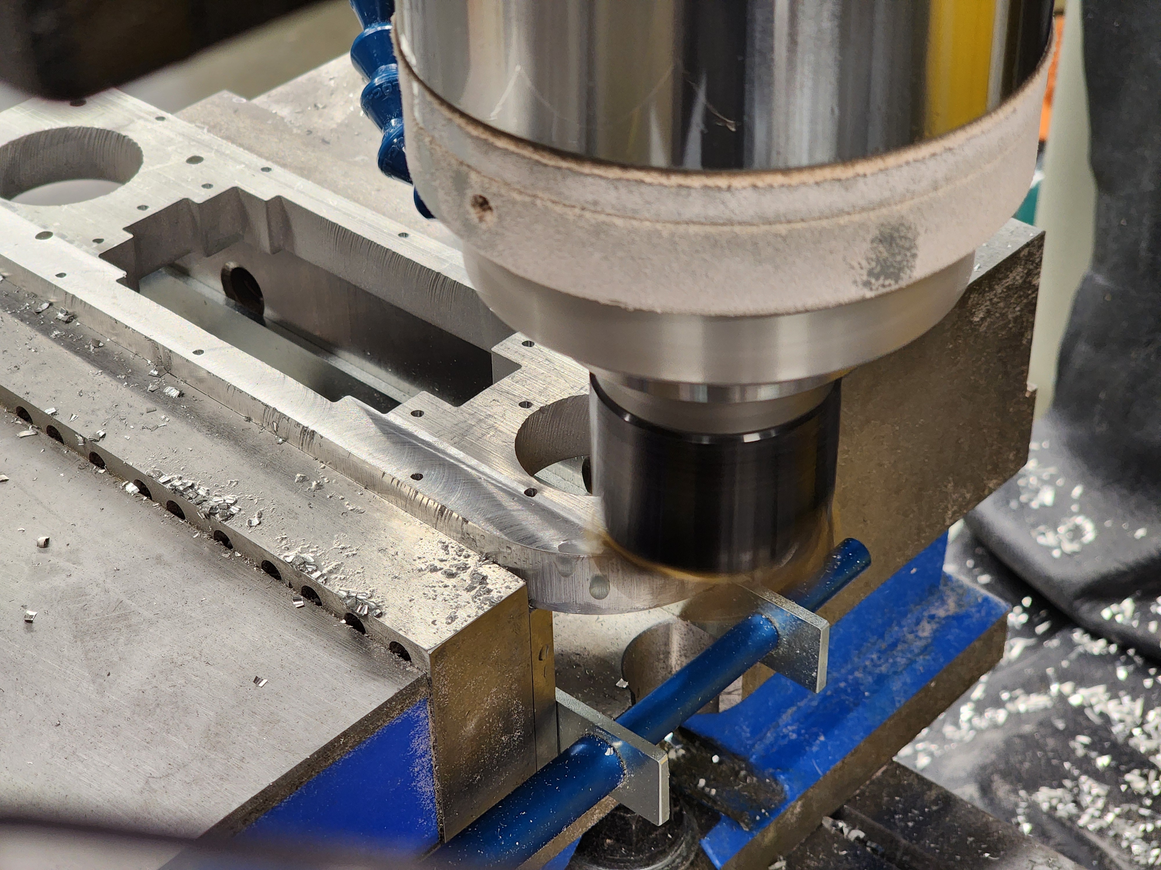
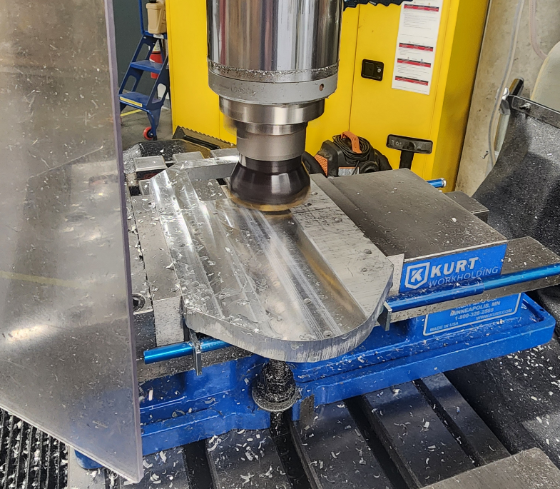
To save cost, I decided on waterjetting the plates out of some aluminum plate stock that I had and then face-milling them to their final thickness.
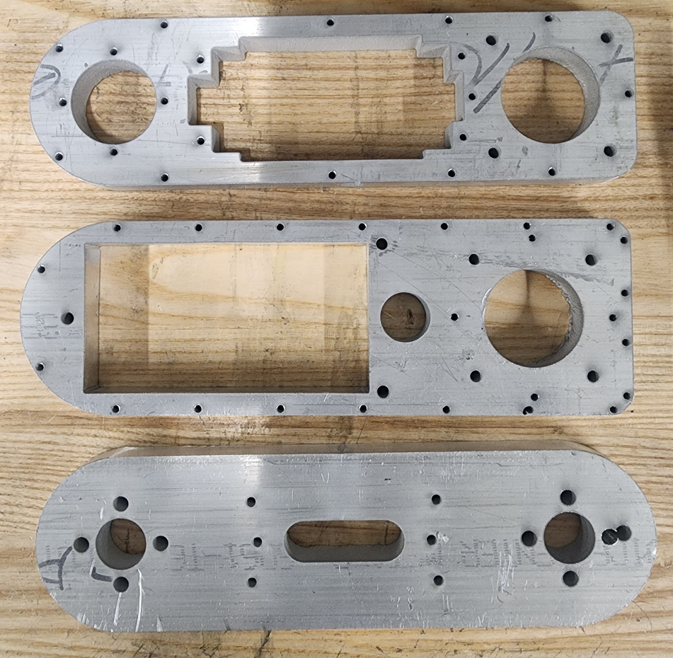
It might be hard to tell in the image, but when cutting these parts, the waterjet service at Iowa State messed up some of the settings, leading to some extremely rough and jagged edges, as well as one location where a hole was cut in the completely wrong place (seen in the bottom right).
When it came to post-machining, I face-milled both sides down to final dimension. Here you can more clearly see the jagged edges from the waterjet.
One thing to note is that using the waterjet to cut the 2D profile of these plates was indeed a lot cheaper and faster, but if I were to do this again, I would have CNC machined the plates entirely to guarantee the positional accuracy of all the holes. A large problem I had with this project was not having a true datum to reference on these parts for a robot requiring this level of precision.
Once all the arm plates were done, I was able to do a quick test fit with the crossed-roller bearings I purchased to support the large moment load of the arm. One thing to note is that I assembled this before deciding to move the elbow motor to the base and use the belt reduction I discussed earlier.
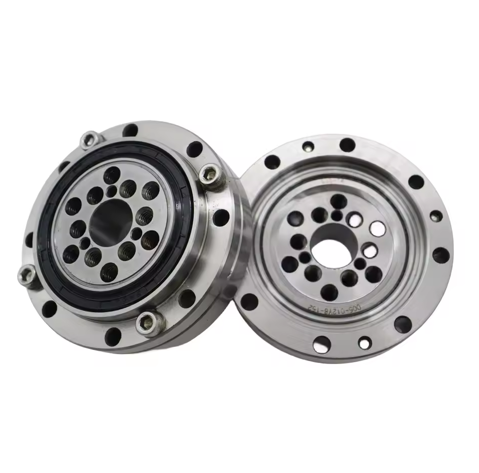
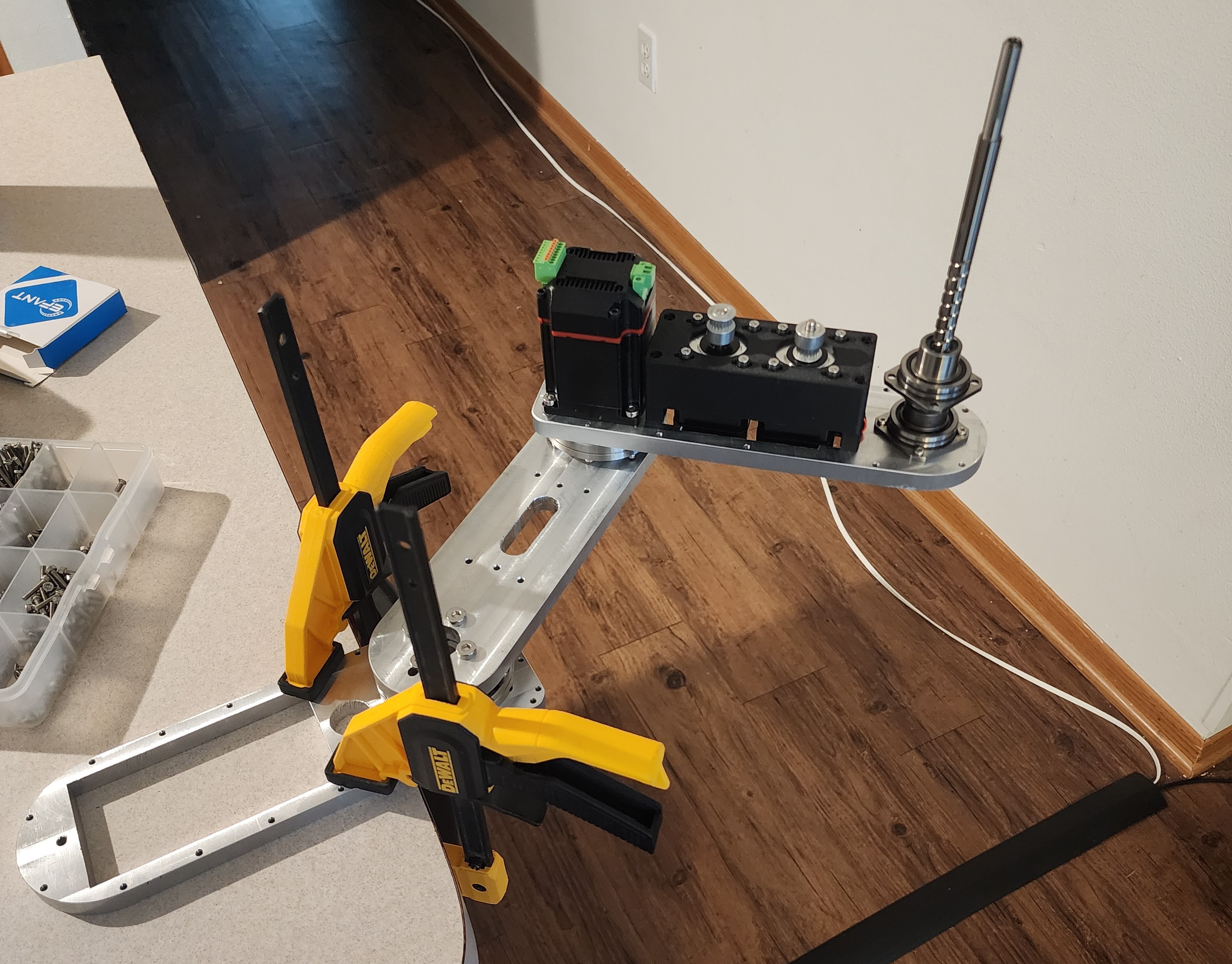
Photo of the crossed roller bearings and the test fit of all the machined components.
The base plate was made after all the other parts, but as it didn't have any extremely critical dimensions, I decided to also waterjet it. Luckily, this time, I was able to talk with the technicians and better tune the waterjet settings for the material, so it came out great.
Motor Coupling
I wanted the coupling from the motor to the crossed-roller bearings I was using to fit accurately and not wear or bend under the torque of the arm. As luck would have it, right when I was getting around to designing a solution for this, PCBWay emailed me and said that they would love to support the project.
I took them up on the offer, designed a CNC-machined coupler, and sent it over to them to manufacture. Two weeks later, the shaft coupler arrived.
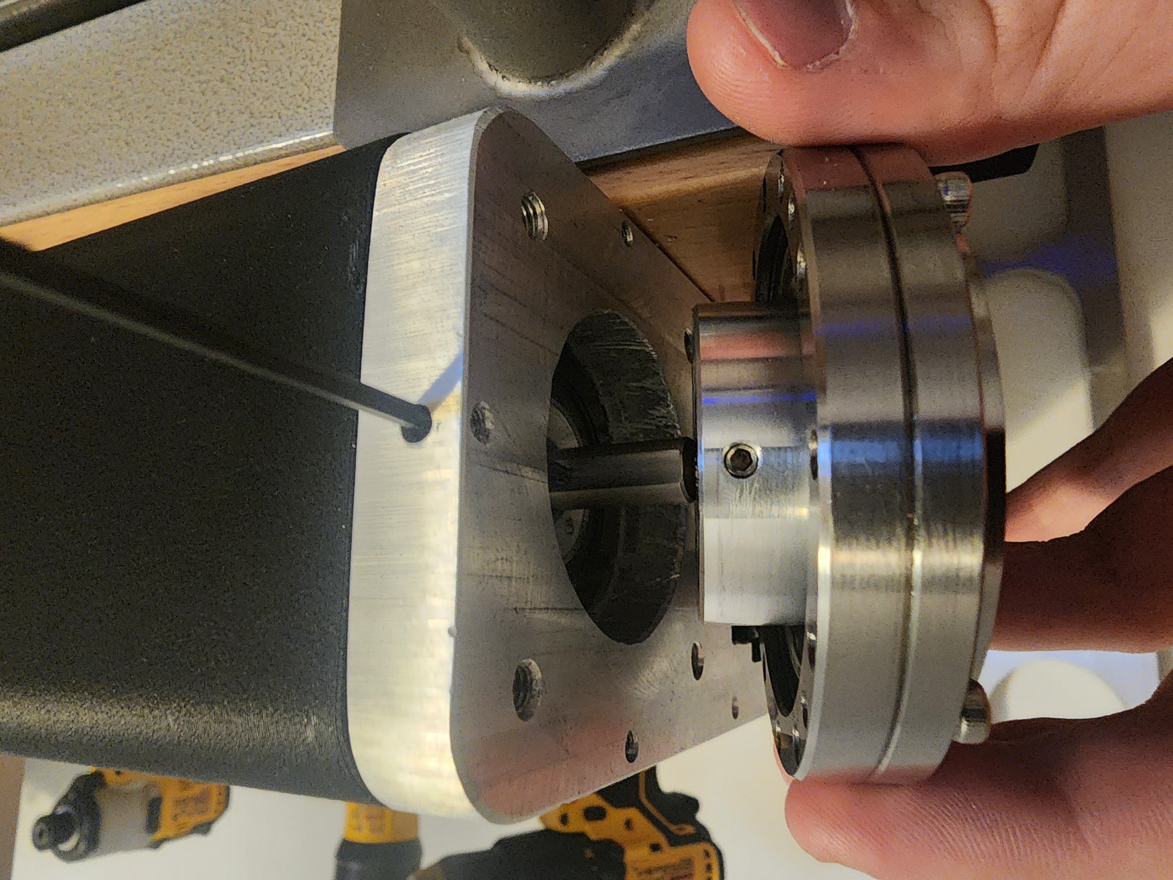
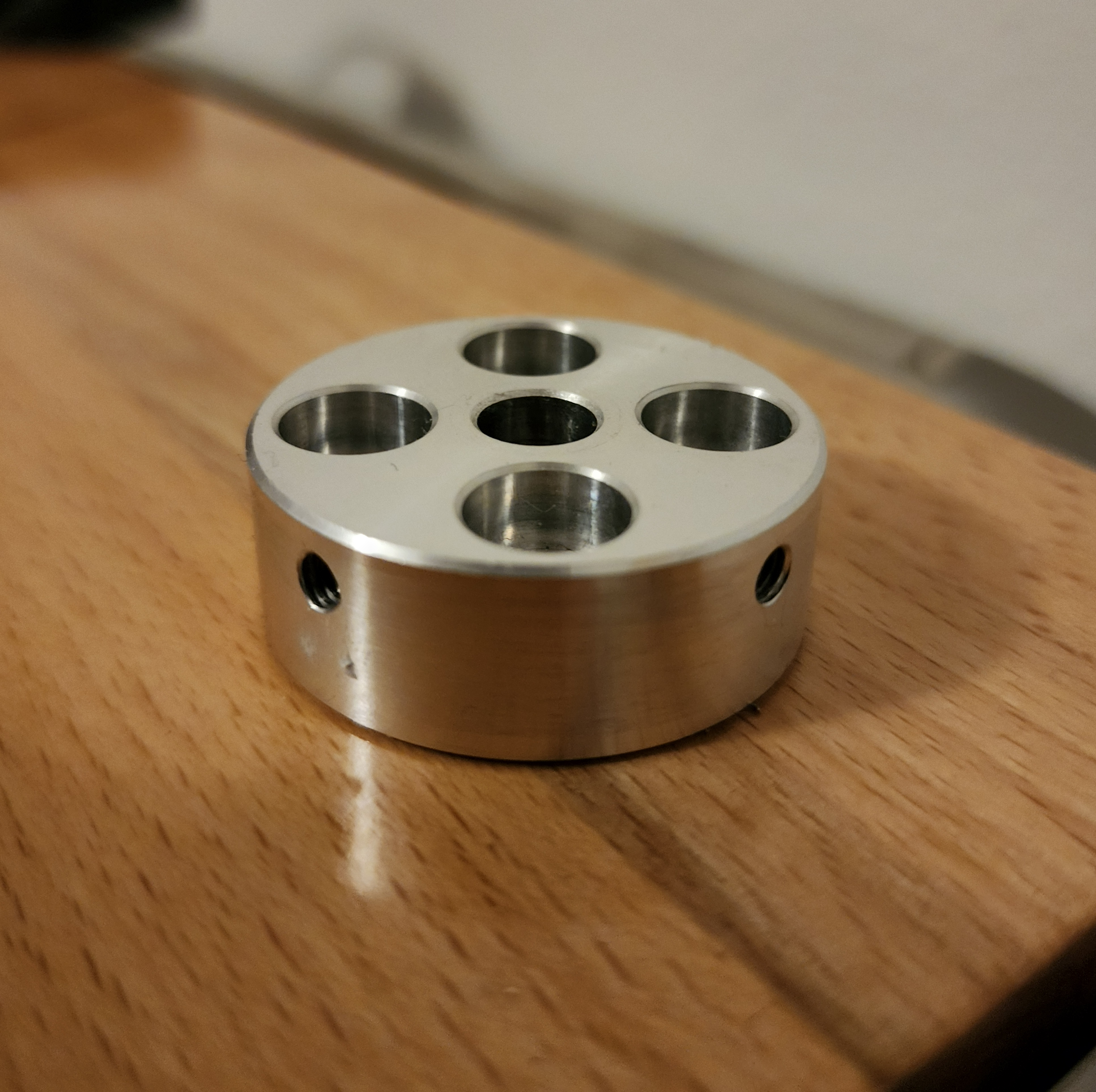
Photos of the motor coupling and the installation
The part came out perfectly, with every critical dimension I specified well within tolerance. From this experience, I can already start thinking about using their services for manufacturing things I cannot make myself, such as metal 3D printing or more CNC-machined parts. Full disclosure: PCBWay did send the parts over but is not paying or requiring me to promote their service. That said, if you're interested in making some cool parts, I would definitely recommend their services.

3D Printed Parts
This project really put my 3D printer to work. Nearly every 3D-printed part on the robot went through countless revisions to reach the final design. This project has definitely set a new personal record for the number of failed attempts and revisions needed. Here is an image of all the failed prints I accumulated over the past year.
Assembly and Testing
Here are some pictures of the final assembled robot.
Closeups and internals of various parts of the arm
Testing and Demo
The first test I wanted to run was simple: moving around some screw organizer bins I had laying around to test the positional accuracy of the robot. Here is a timelapse of a 30-minute test I ran, with the robot continuously moving these bins around without losing its position.
30x Speed Positional Accuracy Test
Here is a demo I did of the arm moving around a Wiimote and a small anvil.
SCARA Arm Demo
Future Improvements
There are still some areas where I think this project could be improved. Firstly, the amount of work I put into making the gearboxes for this project led me to a design with incredibly low backlash for how compact it is, especially considering it's fully 3D-printed.
However, the kinematics of a SCARA arm are quite unforgiving regarding how little backlash is acceptable. If this project's budget were higher, I would have liked to use off-the-shelf harmonic gearboxes or all-in-one harmonic servo actuators.
Given that these are incredibly expensive, they were outside the budget for this project. But, if there is anyone reading this who makes robotic actuators or servos, I'd always be open to working together.
Conclusion
As much as this project has been the bane of my existence for the past couple of years, I really enjoyed working on it and learned a ton. I have never done a large project that incorporated so many different skills. I learned many new things through this project: new CAD techniques, machining the aluminum parts, robot design and kinematics, and programming an entire control application and firmware.
I am quite impressed with the end result, too. I think I accomplished most of the goals that I set, and I still can't get over seeing a robot arm move around, knowing I made it from scratch.
Thanks for reading! Leave a comment or check out some of my other posts below.
]]>This project is a continuation of my previous axial flux motor project. If you've not yet read that I would recommend doing so.
 Caden Kraft
After I was finished with making my last motor project I was quite proud of the results. However, while the motor could achieve extremely high RPM's, this came at the cost of torque.
Originally I thought about rewinding the stator and possible improvements via stronger magnets and/or Iron based 3D printer filament for the stator coils among other things.
Deciding on a Gearbox
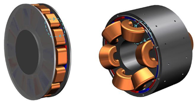
Wanting to work on something a little more different than pure motor design and not wanting to rewind any coils, I set my sights on developing a gearbox that could be integrated into my current stator design. There were 3 primary options that I was looking into when deciding what gearbox that I was going to make, Planetary, Cycloidal, and Harmonic.
Cycloidal (left), Harmonic (center), Planetary (right)
All of these options definitely seem like good ideas but I had to narrow down which one I was going to choose.
Planetary would have been the easiest and probably would have performed the best but I cut it out because I didn't really find it interesting enough and wanted to learn more about the other gearboxes.
While I admire the simplicity of the harmonic drive I was wary of my ability to manufacture the flexible parts needed. I eventually chose the cycloidal drive because it seemed like the biggest technical challenge to design as well as the fact that it looks extremely cool. Cycloidal gearboxes also have nearly no backlash which definitely made it stand out against something like a planetary gearbox with the tolerances of 3D printed parts.
Defining Project Requirements
Now that I knew what gearbox I wanted to make I started to define what I wanted the final design to look like.
- Dual cycloidal drive to reduce vibrations
- Integration of motor and gearbox into one assembly
- 70mm Z height restriction to keep a low profile
- 10:1 reduction
- Easy assembly/disassembly (no adhesives)
- Use existing stator design from axial flux motor
Actuator Design
With my requirements set, I moved on to designing the actuator. The base motor design is based on my last axial flux motor so I began modifying that in order for it to fit a gearbox. Next I had to start work on the design of the cycloidal gearbox system itself. This was quite challenging to figure out initially because the cycloid geometry is fully defined off of parametric equations.
This guide was immensely helpful in defining the geometry. After some time I had the parameters for my parametric equations ready to go based on the size and reduction that I wanted.
| Parameter | Variable | Value |
|---|---|---|
| Radius of rotor | $r$ | 67mm |
| Radius of rollers | $r_r$ | 4mm |
| Eccentricity | $e$ | 3mm |
| Number of rollers | $n$ | 10 |
$$\begin{equation}
\small{x = {r}\cos(t) - r_r\cos(t + \psi) - {e}\cos(nt)}
\end{equation}$$
$$\begin{equation}
\small{y = -{r}\sin(t) + r_r\sin(t + \psi) + {e}\sin(nt)}
\end{equation}$$
$$\begin{equation}
\small{\psi = \arctan\left(\frac{\sin((1-n)t)}{\left(\frac{r}{e}\right) - \cos((1-n)t)}\right)}
\end{equation}$$
I made an interactive graph on Desmos where you can visualize different cycloid designs quicker than you can in SOLIDWORKS.
By plotting these parametric equations from $(0 < t < \pi)$ and mirroring the result I ended up with the final geometry needed for my cycloids.
As this design uses two cycloids they actually rotate in the same direction but have inverted eccentricity with the benefit being that a lot of the vibration is canceled out as the center of mass is roughly centered instead of spinning around. This does come at the expense of added complexity.
Now it was time to finally integrate everything together into one cohesive design. One challenge I faced during this process was the admittedly arbitrary height limit that I gave myself.
There were a lot of design revisions in order to get all of the parts to fit in the allotted space. Below is an image showing a cross section of the final design with the plastic 3D printed components highlighted.
As you can see above there are some very tight gaps between a lot of the moving parts inside the gearbox as a result of needing to fit in this Z constraint. Below is an image that should give a better idea of how the motor and gearbox were integrated into a single assembly.
Once I was done combining the gearbox and motor I landed on this final design
Final Design Renders

Manufacturing and Assembly
When it came to actually manufacturing the design I had to go through quite a few prototype parts before I landed on the final geometry. There was a lot of friction problems with so many parts tightly packed together moving at high speeds so a lot of incremental improvements had to be made. Below is a picture of all the failed parts that didn't make it into the project.
However, when I finally did figure out all the issues I was able to assemble and test the actuator. Here are some photos of what the final design looks like assembled.
Different views of the actuator
Testing
Unfortunately I don't currently have access to a dynamometer to do a proper torque test. If I am able to access one I will update this post in the future with the results. Below is a video of me running the actuator on my bench.
I also took a video with the top components removed so you are able to see the cycloids in action.
My general impressions of it are fairly positive as when it's drawing around ~60W I am unable to stop the output with my hand like I easily could on the previous motor. This combined with the cycloidal nature of the gearbox I cannot feel any backlash whatsoever.
Conclusion
I really enjoyed working on this project as it is a culmination of many of the projects I've posted here over the past few years. Being able to take some wire, magnets, and plastic and assemble them in such a way where they generate rotation with enough torque that even I can't easily stop it is a pretty cool feeling and I am pretty proud of how it turned out.
One area that could be improved is the base torque of the motor. Even just reprinting the stator in Iron PLA would yield a higher torque with zero change to the design.
The other area that this actuator suffers in is friction. With the two cycloids spinning around inside the casing there is more rubbing and friction than I initially intended and I think this could be fixed by either only using a single cycloid or making the actuator taller.
I also wish I was able to do more empirical testing on the motor so I could properly characterize its performance but that may have to be a project for another day.
If you enjoyed this project check out some of my other projects that I have completed below!
]]>As I've continued working on the Iowa State Solar Car team one problem on our current car I have noticed is how we handle routing the high voltage connections in our battery pack. This project aims to create a design that consolidates our HV connections and makes maintenance significantly easier.
The current problem
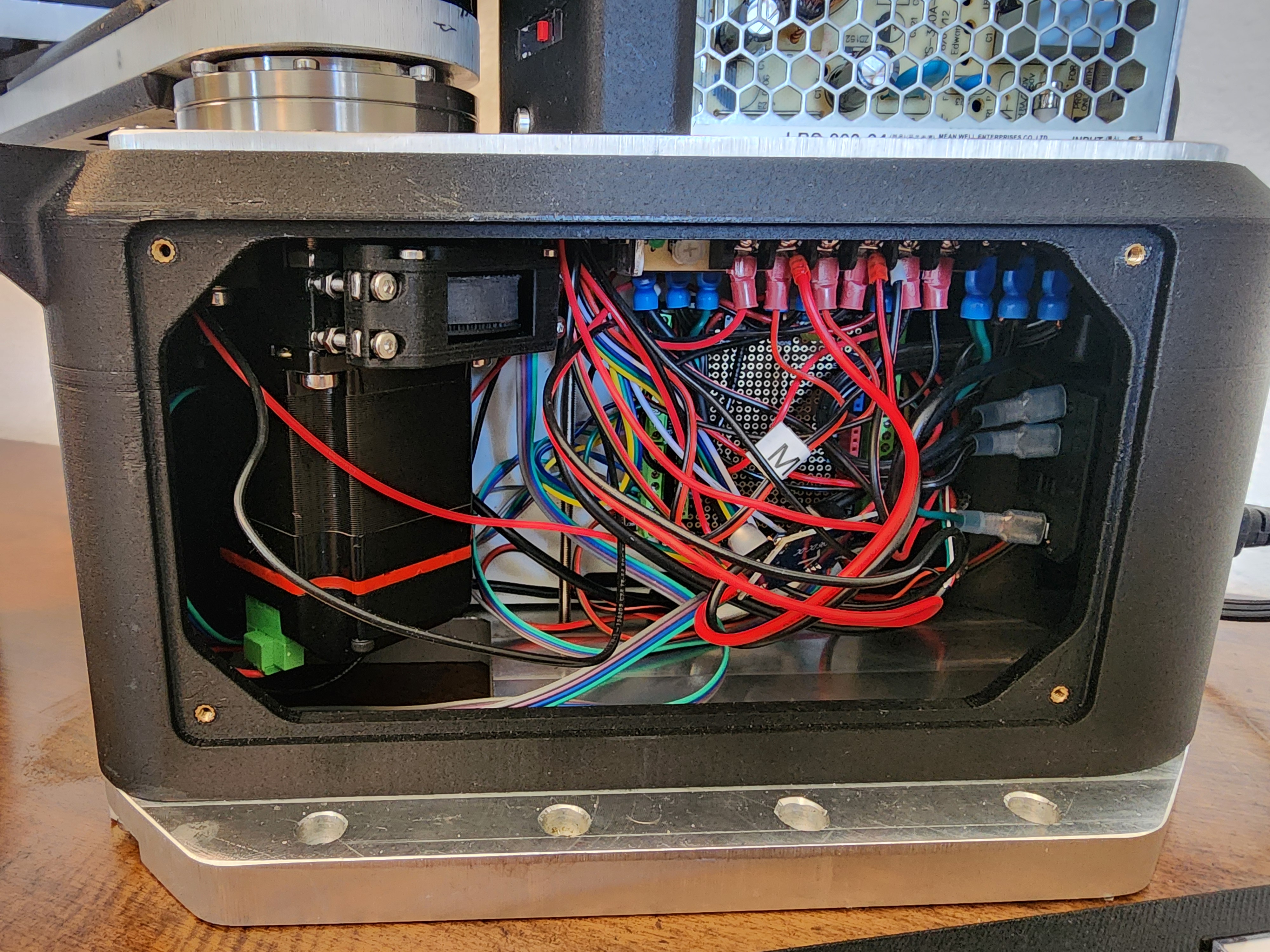
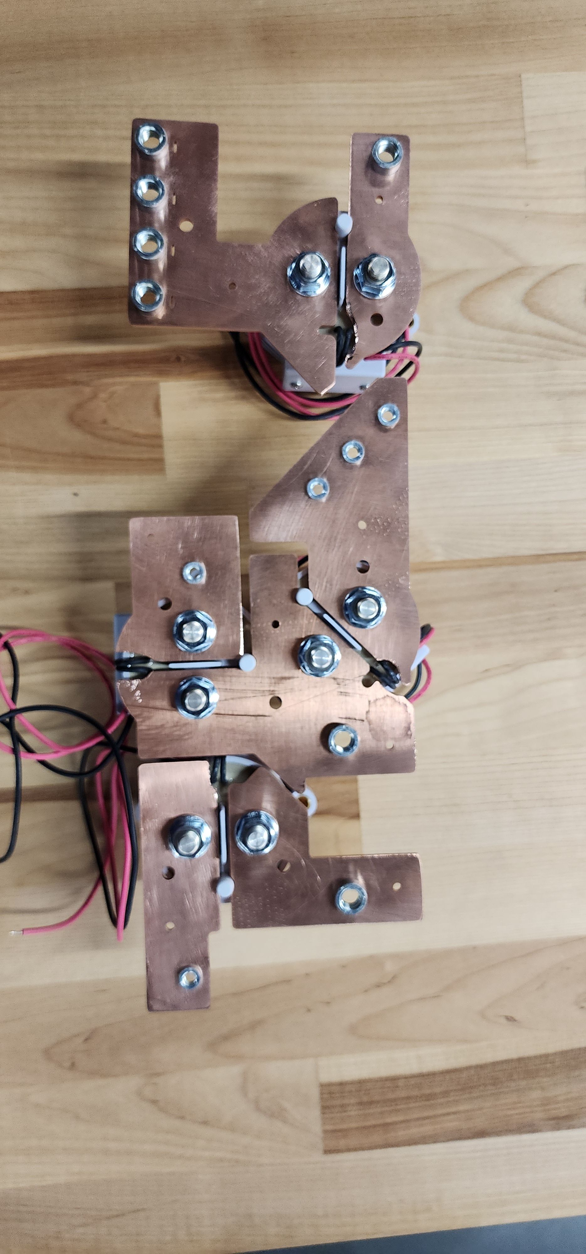
As you can see below, currently we have a mess of 1/0 gauge wire sprawling between countless contactors, fuses, current sensors, and connectors. This network of wire is used for connecting our battery pack to our motors, chargers, solar array, and LV systems. What we currently have is a nightmare to work with and makes seemingly simple tasks such as changing fuses an hour long ordeal.

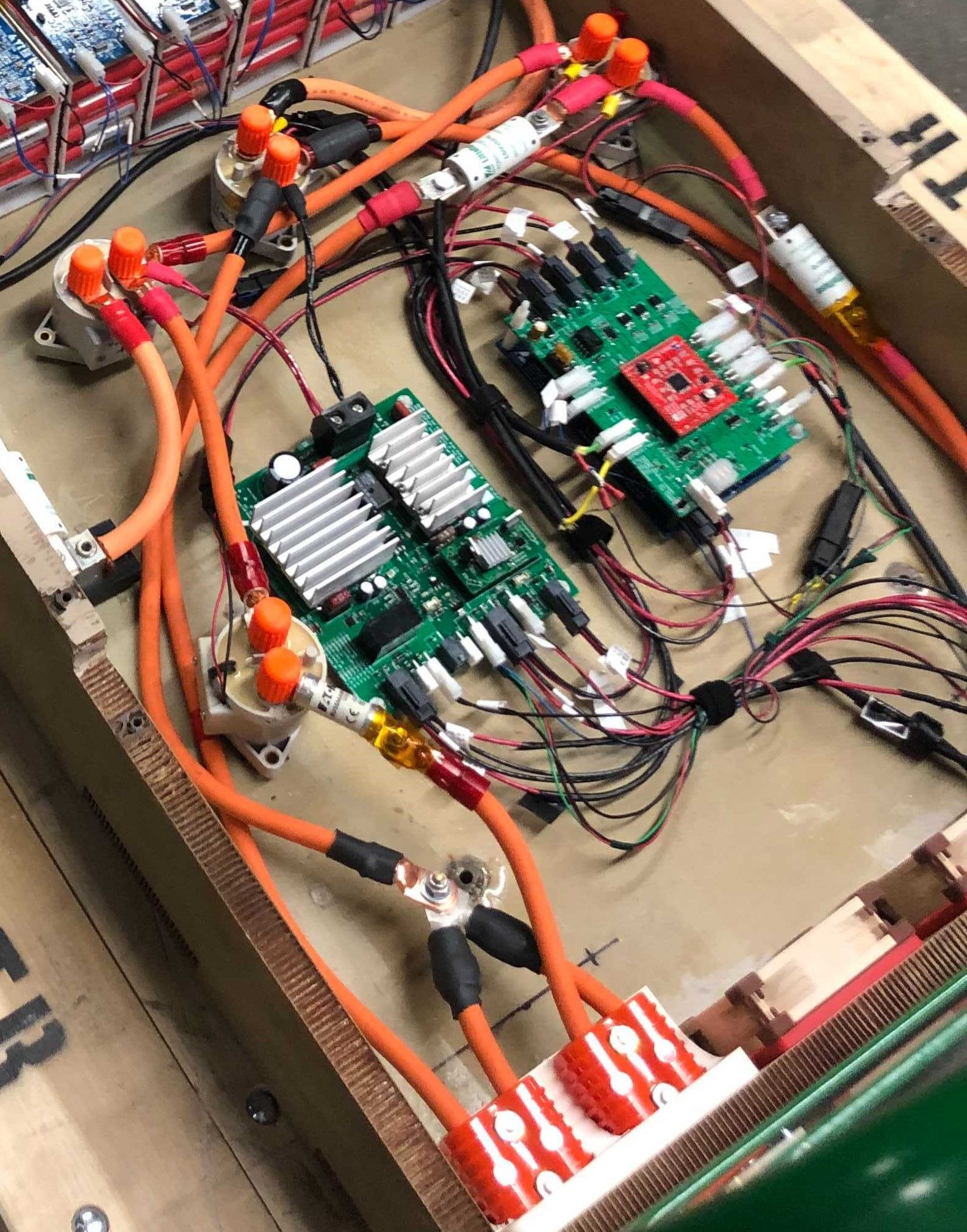
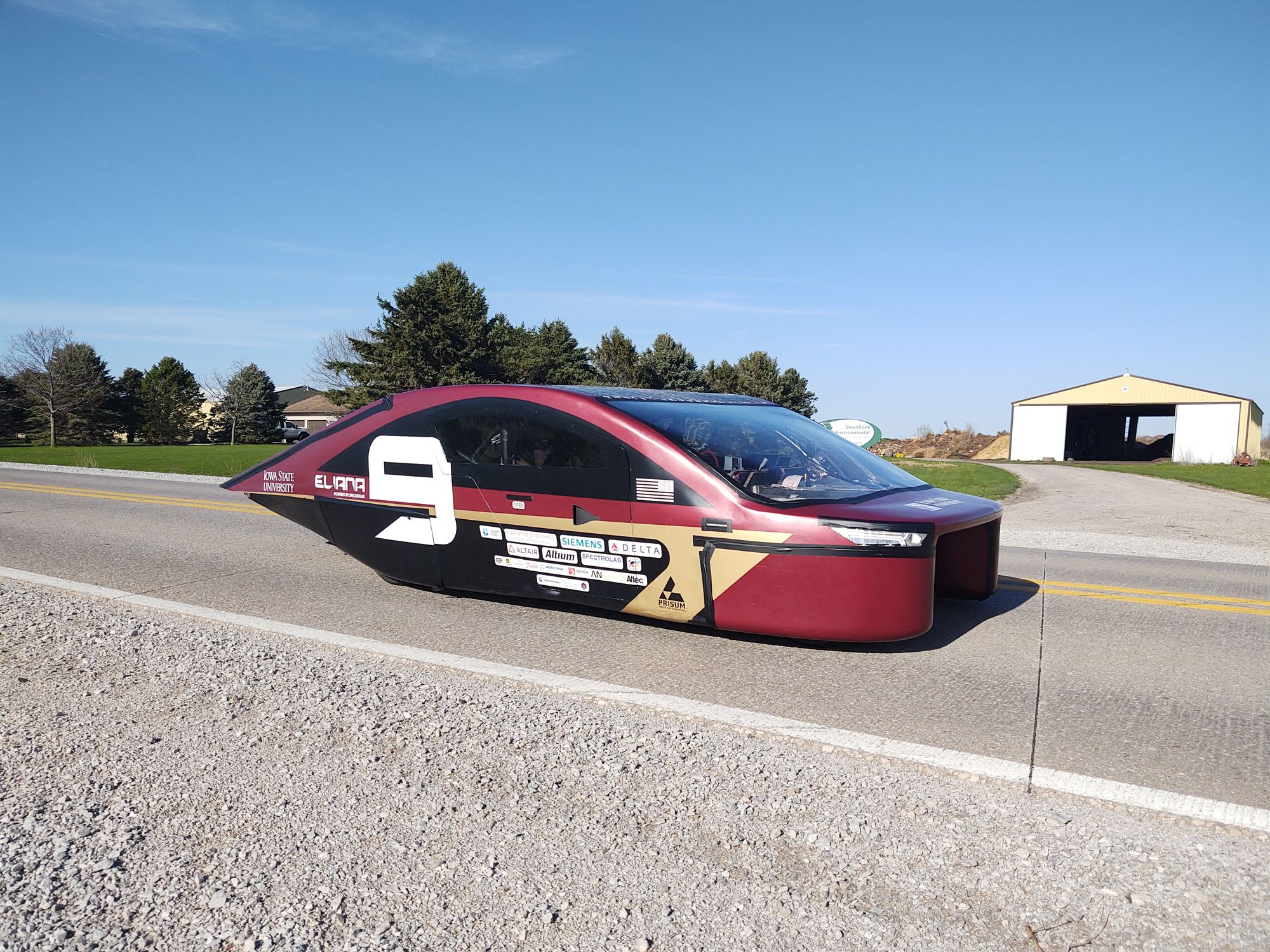
Current Solar Car, P15 Eliana (left), Current HV Dumpster Fire (Right)
The main reason that our current setup is such a mess is because the American Solar Challenge regulations require contactors and fuses at most points through the HV chain leading to many breaks between wires. We also have a problem where the specialty fuses we have to buy do not have fuse holders available so we have to put them inline in a wire as seen above.
Solution Requirements
Below are the requirements I came up with for the design of the HV bussing solution.
- No doubling up cables on a single screw terminal
- Properly sized lugs and wire gauge based on the connection
- Captive, clinched, or crimped nuts for the bolted connections
- Dedicated holders for all current sensors and fuses
- Automotive grade panel mount connectors
- Use bus bars over cables whenever possible
- Integrated Compact Design
One of the challenges with creating a design for this was deciding on contactors, fuses, and current sensors. Below is what I decided on.
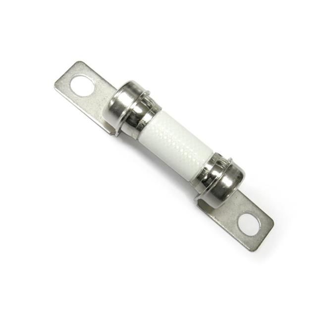
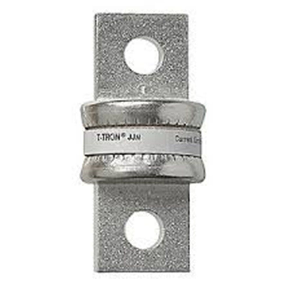
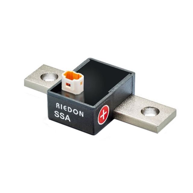
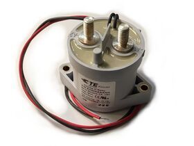
Littlefuse 526 Series (Motors, Array, Charging) TL, Edison TJN-100 (Main) TR, Riedon SSA-250 Current Sense BL, Kilovac EV200 Contactor BR
Out of all these the 15-50a fuses were definitely the hardest to find as I wanted all of these fuses to have the same form factor and be able to mount via bolted joint. The Littlefuse 526 series is the only one online that is able to meet these requirements and it just so happens to be designed specifically for electric vehicles.
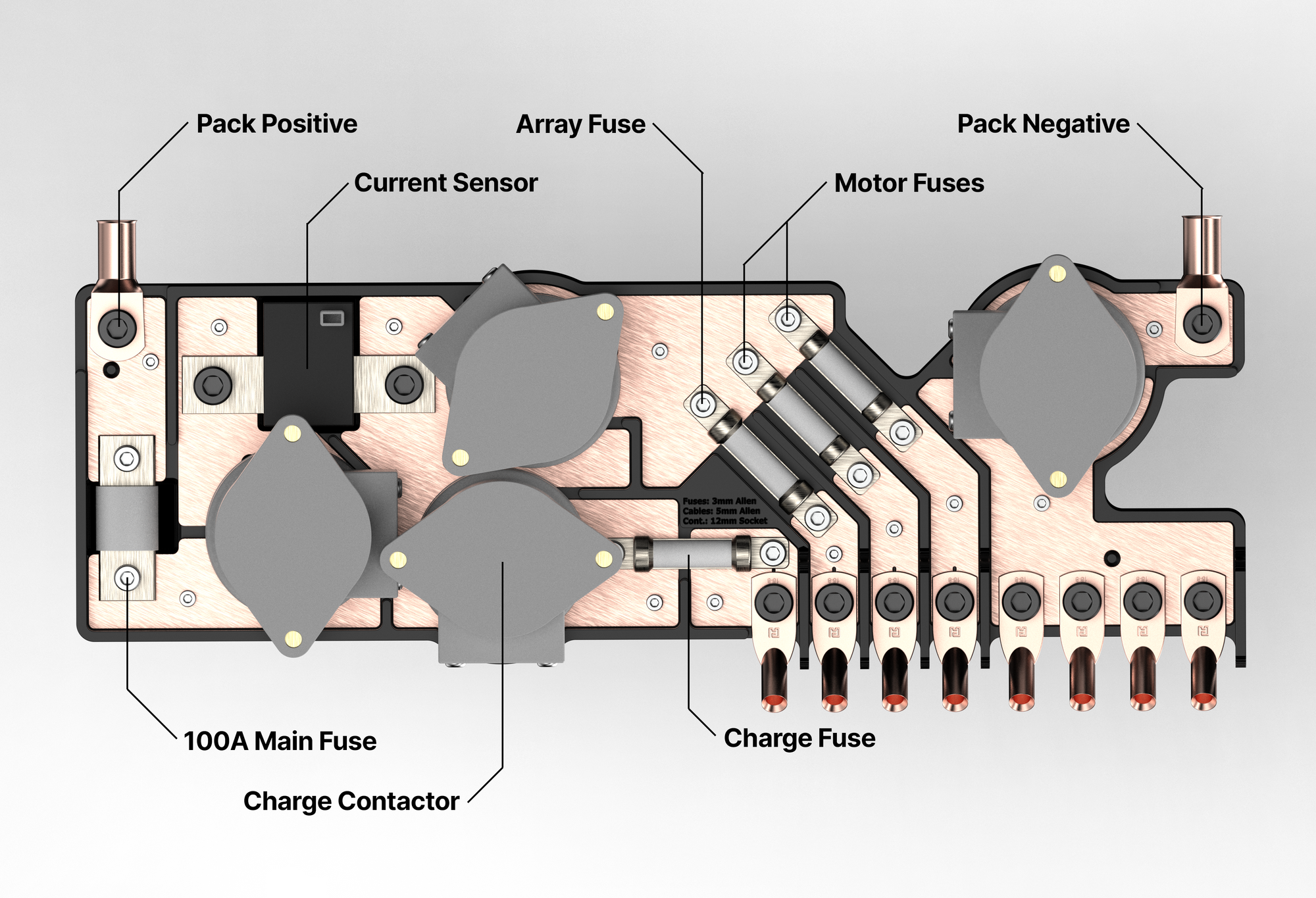
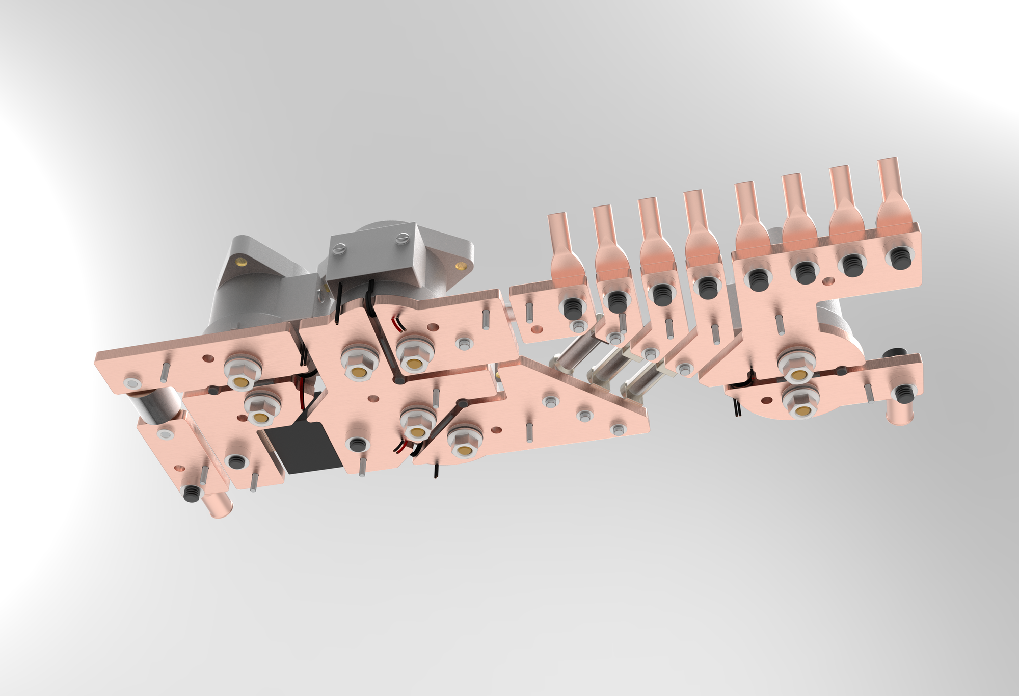
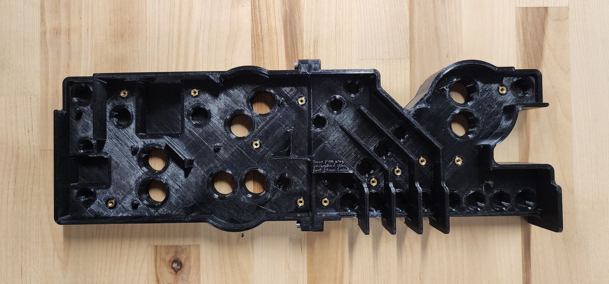
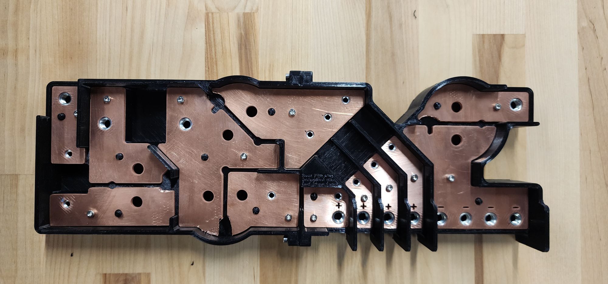
Below is the design that I came up with for the final bus bar network.
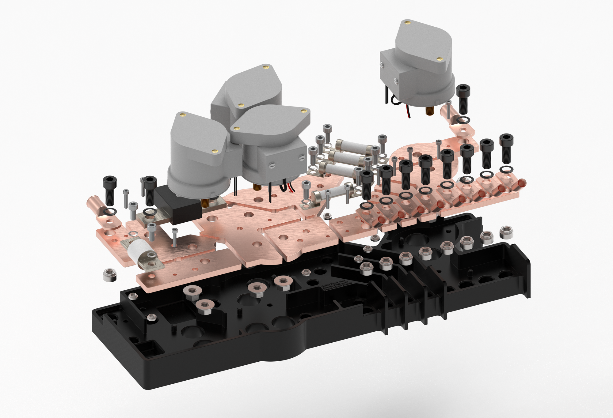
Assembly
For the assembly I chose to use clinch nuts on the copper that allow for the nuts to be embedded into the bus bars and reduce the need for you to use a wrench on each side to tighten the fuses in place.
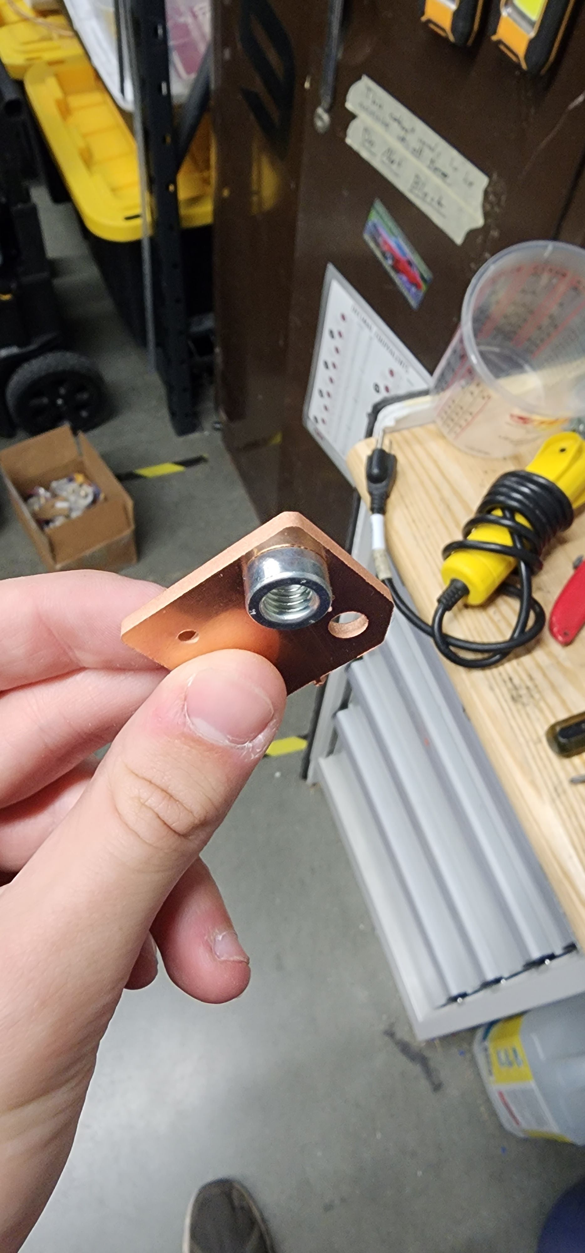
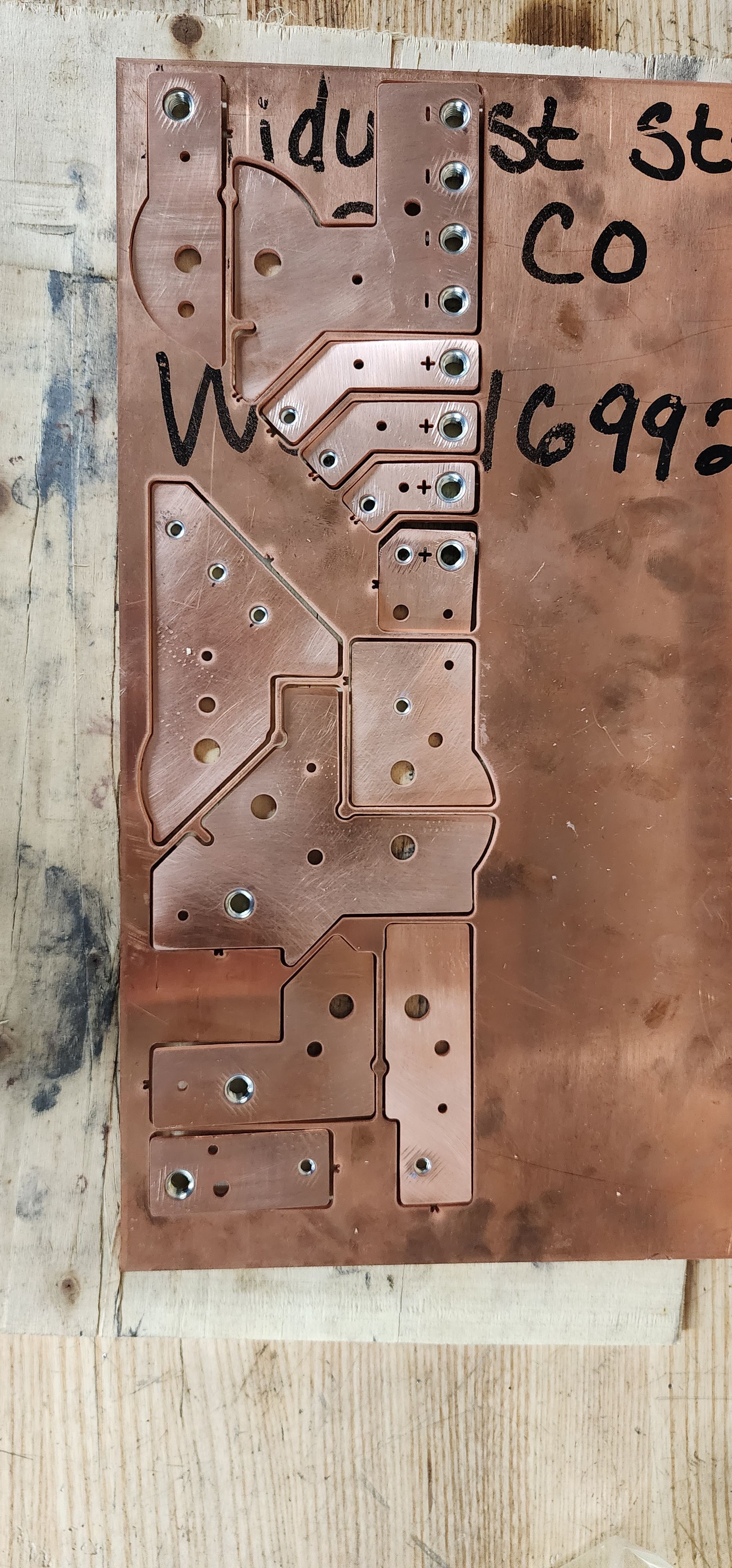
All the waterjet components as well as clinch nut installation
For the tray I designed it to be 3D printed in two parts out of PETG. There is a M3 Heat-set insert and datum pin for each bus bar to keep everything aligned as well as walls between all the bus bars to prevent shorting. As metric hardware is something we don't use fairly often I also included the allen key and socket sizes needed to do repairs embossed into the print.
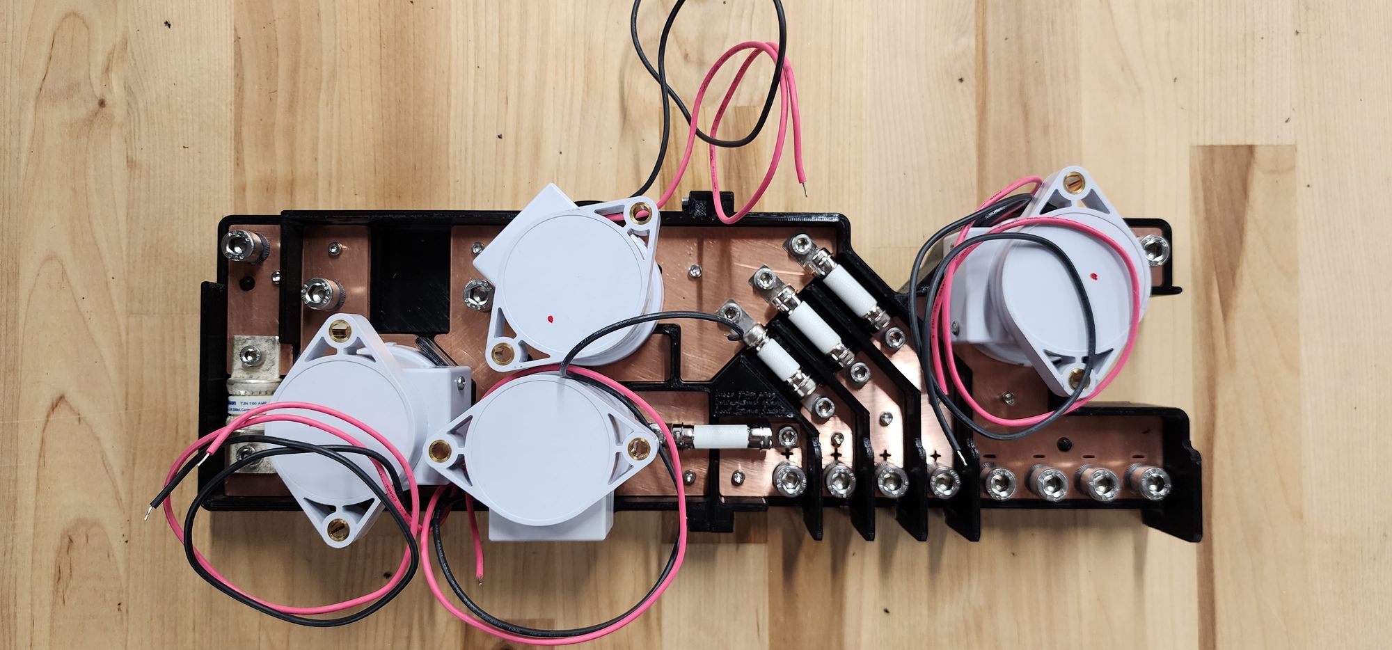
In its current state it is nearly done but is still waiting on the current sensor as well as routing all the wires and hooking it up into our battery pack. I think it should work well and will be the standard for our team's battery pack design moving forward.
Conclusion
Overall I really enjoyed this project and am glad that it greatly simplifies the design of our battery pack. I used quite a few CAD techniques I hadn't before to model the bus bars and tray. I am quite proud of how everything turned out as all the parts went together perfectly and the final design ended up being pretty clean.
To see some of the other solar car work that I've done as well as my other projects click the links below.
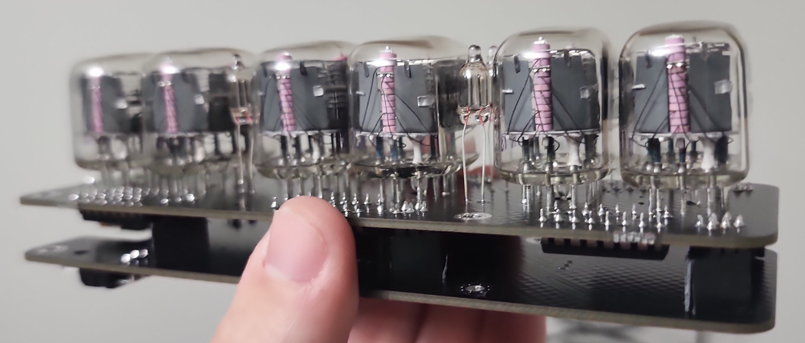
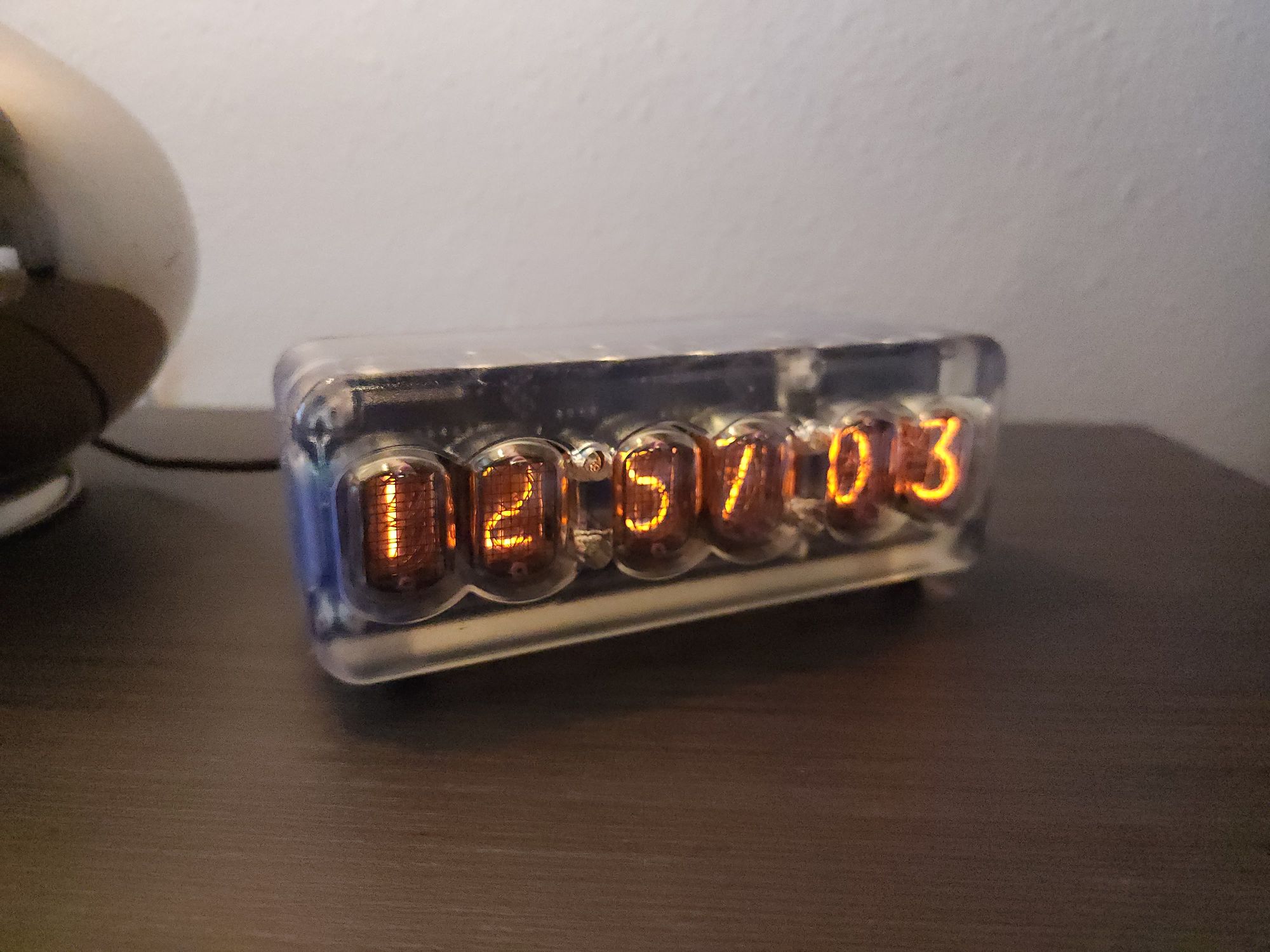
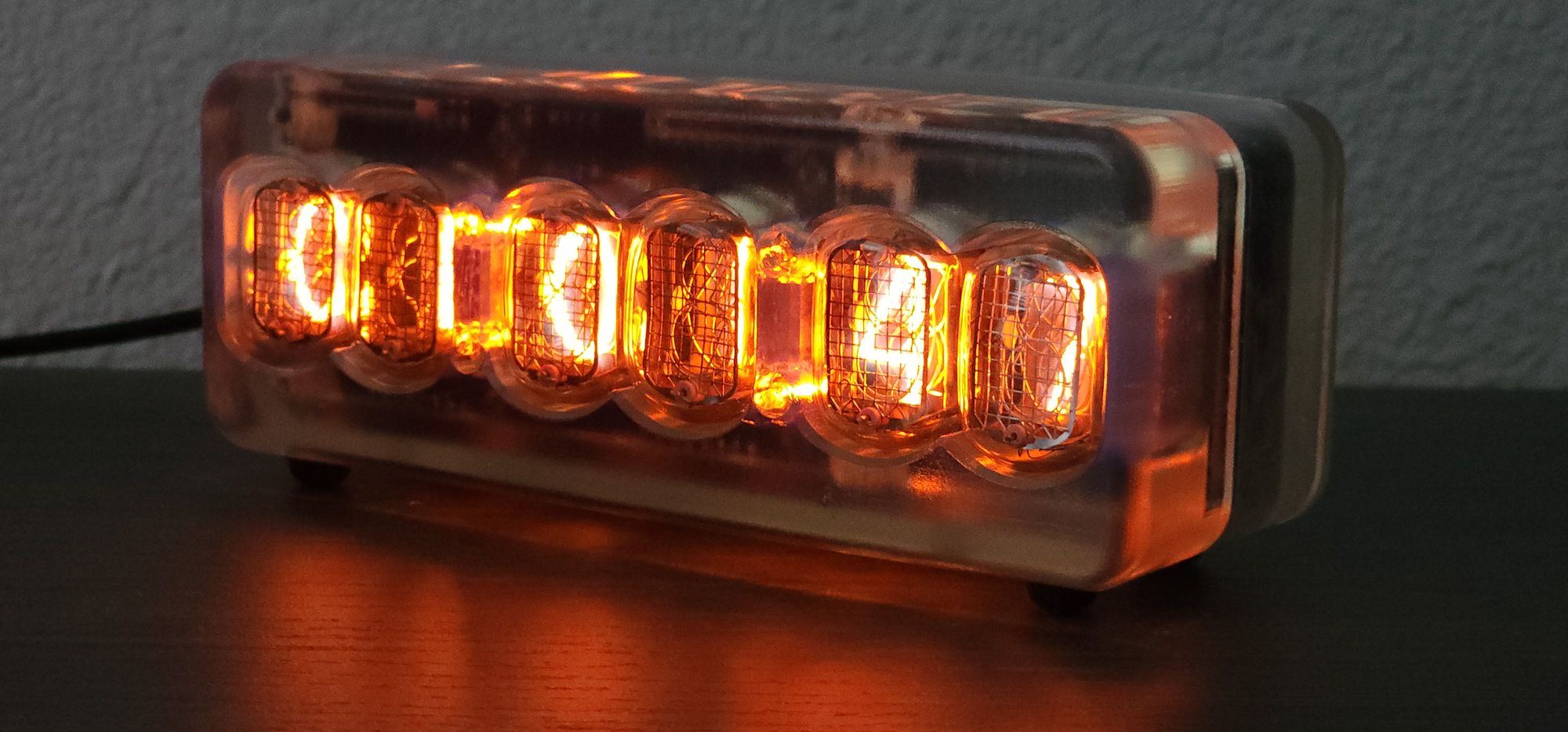
]]>I have always thought that nixie tubes are one of the coolest inventions ever made. The novelty of having such an intricate assembly of blown glass and spot welded numbers just to simply display digits is something I've always admired.
What's a Nixie Tube?
Before the invention of the LED or the seven segment display, engineers needed a device capable of displaying digits for things like voltmeters, multimeters, and frequency counters.
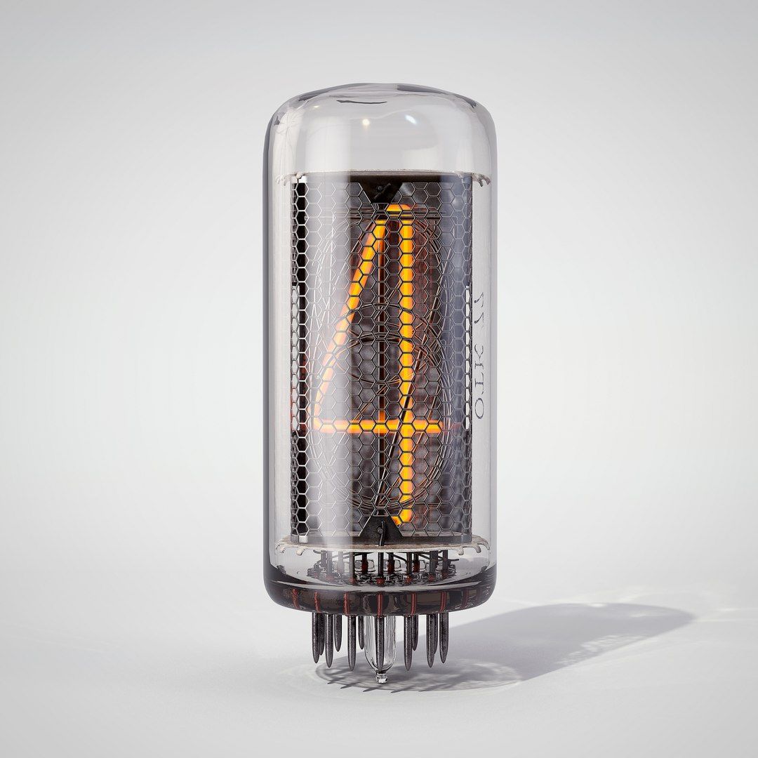
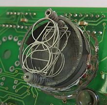
IN-18 Nixie (left), Broken GN-4 (center), GN-4 Cycling through digits (right)
To solve this problem Engineers in the USSR created nixie tubes which were made of 10 digits encased in blown glass that was sealed with Neon gas. The tubes have a wire mesh anode with multiple digits acting as the cathodes. When voltage is applied across the two the Neon gas directly around the digit glows.
Project Requirements
I've looked into simply purchasing a nixie tube clock in the past but there were always a few key wants that I had for a clock that could not be found in available models online.
The project requirements I've set for this clock are listed below.
- 6 Digits in order to display seconds
- Neon bulb colons between the hours, minutes, and seconds
- WiFi, or atomic capability to have a perfect synchronized time
I decided to use the IN-12 nixie tube due to its relatively low cost and the horizontal mounting making them ideal for the design I had in mind.

For the time accuracy I decided on using the Raspberry Pi Pico W and using the WiFi capability to sync to NTP time servers.
Design
For the design I started on the PCB side of things as that is what I was less familiar with. To drive the nixie tubes I decided on using the K155ID1 nixie tube driver. For the power supply I decided on using the NCH8200HV. Finally, for the colons I decided on using NE-2 bulbs.
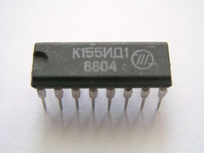
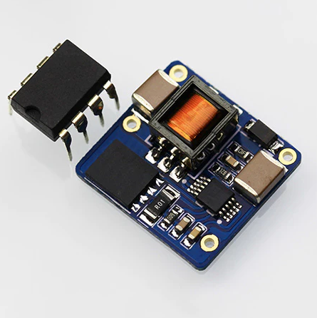
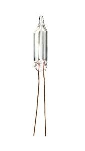
K155ID1 (left), NCH8200HV (center), NE-2 bulb (right)
After a few design revisions this is the final PCB and schematic that I came up with.
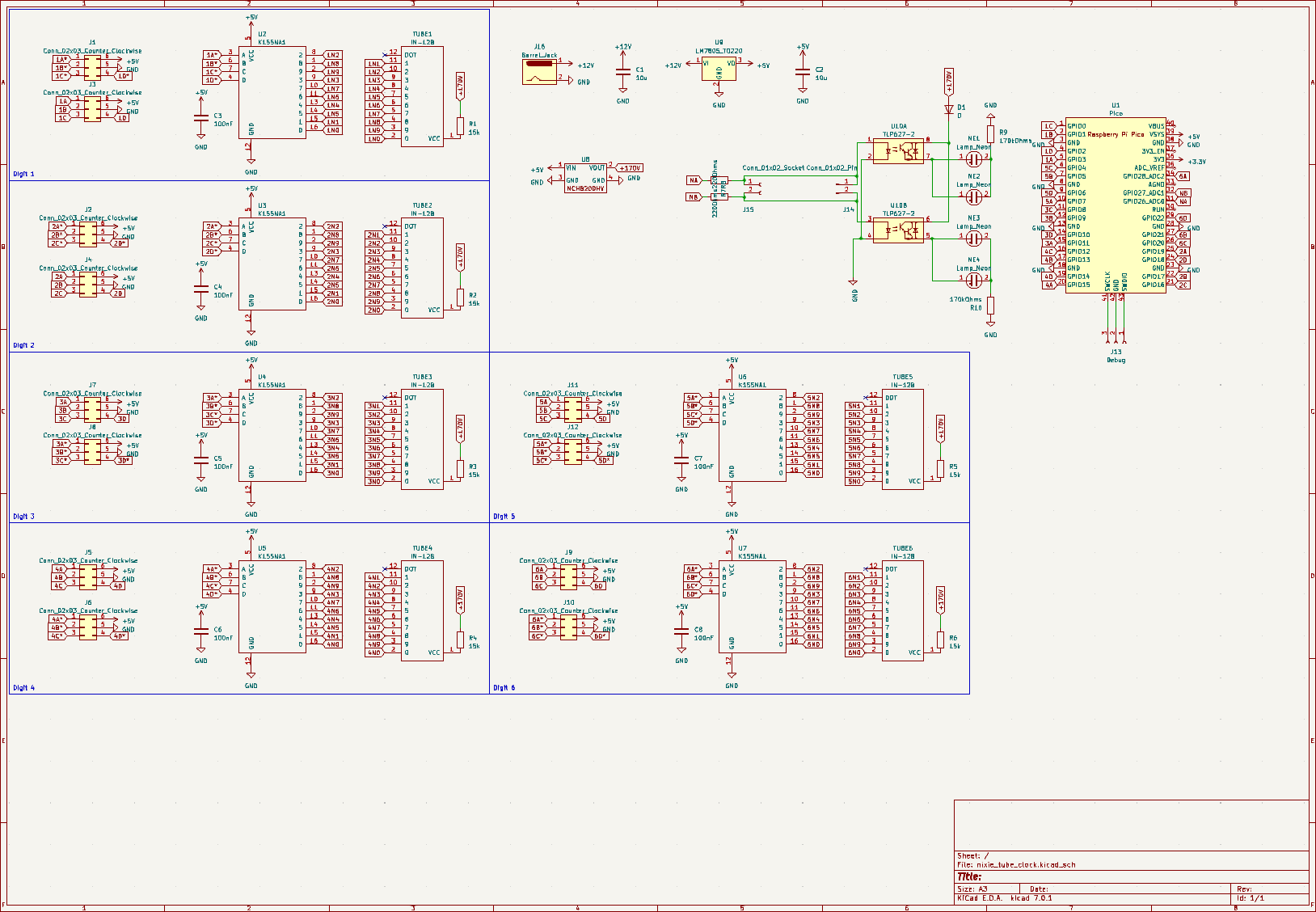

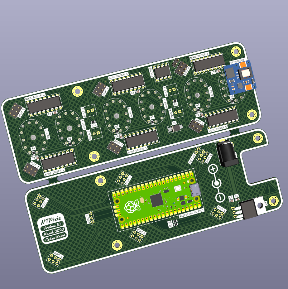
Schematic (left), PCB layout (center), 3D View (right)
To save cost on ordering the PCB I decided to design it to be snapped in half and then both pieces stacked on top of each other connected via B2B connectors.
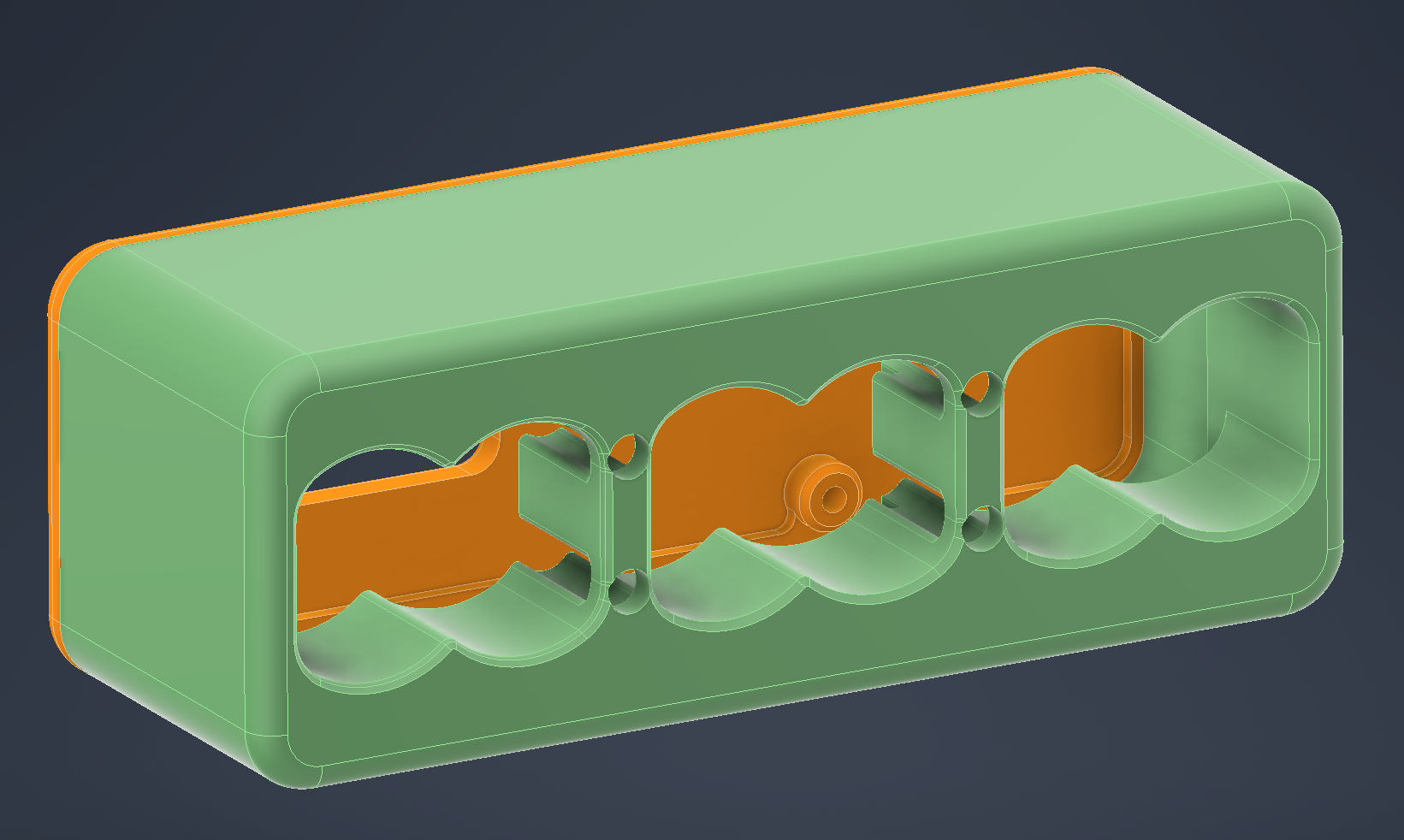
As for the design of the case, I was originally thinking of making a wooden case but did not have a wood shop at my disposal so I decided on making a clear resin SLA enclosure to sell the retro N64 look. The final case design I came up with is below.
Firmware
For this project I decided to use MicroPython on the Pico as it has more documentation and support online for this type of project. Below is the code I wrote for the firmware running on the clock.
import network
import ntptime
from machine import Pin, Timer
from time import localtime, sleep, time

# Define the pins for each nixie tube

nixie_pins = [
    [6, 4, 5, 7],  # nixie tube 1
    [22, 20, 21, 28],  # nixie tube 2
    [2, 0, 1, 3],  # nixie tube 3
    [18, 16, 17, 19],  # nixie tube 4
    [10, 8, 9, 11],  # nixie tube 5
    [14, 12, 13, 15]  # nixie tube 6
]

colon_pin_1 = Pin(26, Pin.OUT)
colon_pin_2 = Pin(27, Pin.OUT)

# Define the lookup table for digit to binary conversion
digit_to_binary = {
    0: [0, 0, 0, 0],
    1: [0, 0, 0, 1],
    2: [0, 0, 1, 0],
    3: [0, 0, 1, 1],
    4: [0, 1, 0, 0],
    5: [0, 1, 0, 1],
    6: [0, 1, 1, 0],
    7: [0, 1, 1, 1],
    8: [1, 0, 0, 0],
    9: [1, 0, 0, 1]
}

# Connect to Wi-Fi
sta_if = network.WLAN(network.STA_IF)
sta_if.active(True)
sta_if.connect("WIFI_SSID_HERE", "WIFI_PASSCODE_HERE")
while not sta_if.isconnected():
    pass

# Set up the pins for each nixie tube
nixie_tubes = []
for pins in nixie_pins:
    nixie_tube = []
    for pin in pins:
        nixie_tube.append(Pin(pin, Pin.OUT))
    nixie_tubes.append(nixie_tube)
    #print(nixie_tubes)

# Set up a timer to update the display every second
timer = Timer(-1)

ntptime.settime()
# Define a function to update the display
def update_display(timer):
    # Get the current time from the NTP server
    print(time())
    current_time = localtime()
    # Apply the UTC offset (in seconds)
    seconds_offset = 0 #using https://time.is
    utc_offset = -5 * 60 * 60 - seconds_offset # for example, 1 hour ahead of UTC
    # -5 = CST -7 = PST
    current_time = localtime(time() + utc_offset)
    if current_time[4]==10 and current_time[5]==10:
        ntptime.settime()
        print("NTP SYNC")
    if current_time[3]>12:
        twelve_hour_time = current_time[3]-12
    else:
        twelve_hour_time = current_time[3]
    #print(current_time)
    #print(twelve_hour_time)
    # Convert the time to digits
    digits = [
        twelve_hour_time // 10,  # hour tens
        twelve_hour_time % 10,  # hour ones
        current_time[4] // 10,  # minute tens
        current_time[4] % 10,  # minute ones
        current_time[5] // 10,  # second tens
        current_time[5] % 10   # second ones
    ]

# Code below is to cycle less common digits to in order to prevent leaking this section should be reworked some day

    if current_time[3]==3 and current_time[4]==0:
        digits = [0,0,0,0,0,0]
    elif current_time[3]==3 and current_time[4]==1:
        digits = [1,1,1,1,1,1]
    elif current_time[3]==3 and current_time[4]==2:
        digits = [2,2,2,2,2,2]
    elif current_time[3]==3 and current_time[4]==3:
        digits = [3,3,3,3,3,3]
    elif current_time[3]==3 and current_time[4]==4:
        digits = [4,4,4,4,4,4]
    elif current_time[3]==3 and current_time[4]==5:
        digits = [5,5,5,5,5,5]
    elif current_time[3]==3 and current_time[4]==6:
        digits = [6,6,6,6,6,6]
    elif current_time[3]==3 and current_time[4]==7:
        digits = [7,7,7,7,7,7]
    elif current_time[3]==3 and current_time[4]==8:
        digits = [8,8,8,8,8,8]
    elif current_time[3]==3 and current_time[4]==9:
        digits = [9,9,9,9,9,9]

    print(digits)
    # Convert the digits to binary and display them on the nixie tubes
    for i in range(6):
        binary = digit_to_binary[digits[i]]
        for j in range(4):
            nixie_tubes[i][j].value(binary[j])
    colon_pin_1.value(1)
    colon_pin_2.value(1)
    sleep(0.5)
    colon_pin_1.value(0)
    colon_pin_2.value(0)

# Start the timer
timer.init(period=1000, mode=Timer.PERIODIC, callback=update_display)

# Put the device to sleep to save power
while True:
    sleep(1)  # can be interrupted by timer events
Input WiFi SSID, password, and timezone for this code to run
Final Assembly
Below are renders and pictures of the final design up and running.
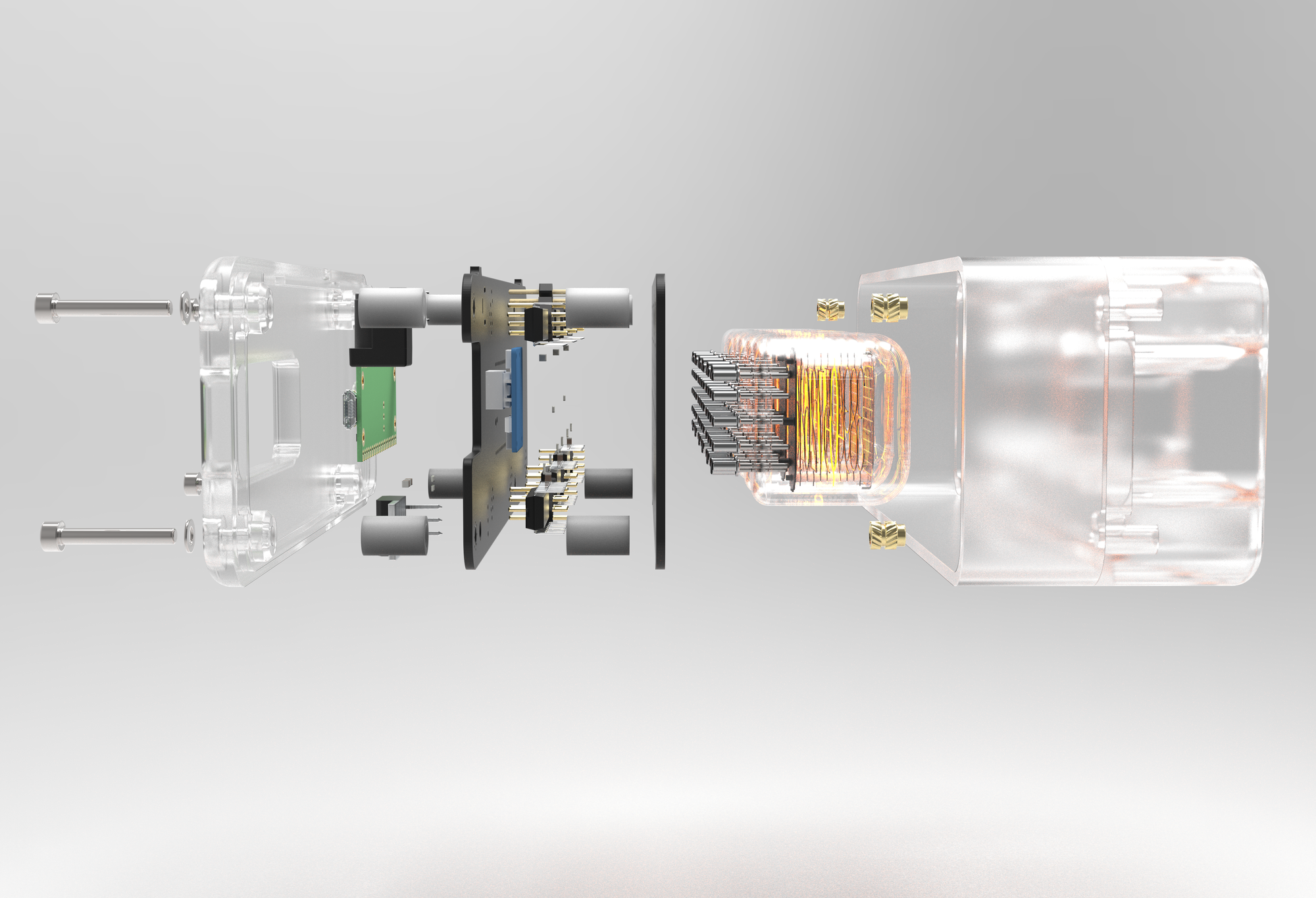
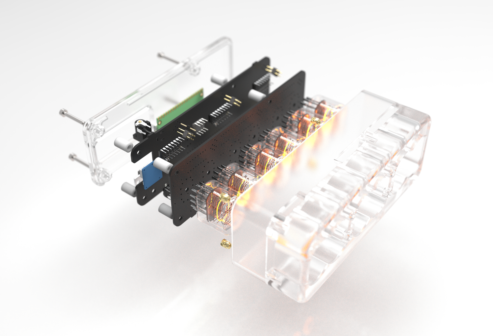
You can see an orbital view of the design by dragging on the model below.

Finished photos of the clock
Conclusions
I have been using it on my bedside for the past few weeks now and it has kept time perfectly and I haven't yet noticed any major issues. One issue I am running into is that two of the four bulbs on the colons don't seem to light up consistently. I've read online about needing time for the bulbs to polarize and as they do turn on some of the time I think that's what the problem is.
This has been one of my favorite projects because it was very interdisciplinary in the amount of skills that I had to use in order to complete it. Second, thanks mostly to the superb quality of the SLA print (plus 2 coats of Rust-Oleum Crystal Clear Enamel), this project looks the most polished and least DIY out of anything I've ever done. This clock allowed me to hone in on my PCB design skills and I hope I can use them more on future projects.
Thanks for reading, please check out some of my other posts below!
]]>After my first custom brushless motor I felt confident enough with the basic theory of how they work to make a second design with significantly more thought and math defining the design.
 Caden Kraft
As my first design was made by looking at images online and implementing dimensions based on what looked right I found that there were some serious inefficiencies that could be remedied with a bit of math.
Why Axial Flux?
One of the main reasons that I chose to use an axial flux motor design was because the air gap between the magnets and the coils is more or less two dimensional. As opposed to a traditional radial flux motor this allows me to adjust the air gap with shims instead of redesigning the rotor every time to adjust it.
Another benefit to this design is that because this is a DIY project I do not have the budget to order the custom magnets with a bend for a radial flux rotor.
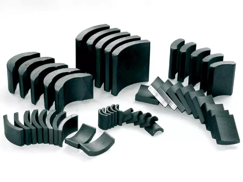
The flat nature of an axial flux motor allows me to use traditional rectangular bar magnets that can be found cheaply online in large quantities without the need to have them custom made.
Coreless Design and Halbach Array
Similarly to the magnets, due to cost constraints for this project and the manufacturing capability that I currently have in my college apartment, I am not able to custom make ferrite or steel laminate ferrous cores inside the coils.
As a ferrous core is extremely important in shaping the magnetic field around the coils, I had to research a different solution to remedy this and came across the Halbach magnet array. This works by alternating the magnet poles by 90 degrees at a time instead of 180 degrees like normal designs.
This uses extra magnets to shape the magnetic field as a iron core traditionally would. As there are very little designs on the internet that I could find the utilize a Halbach pattern I chose to implement it into my design to hopefully contribute some experience implementing it into a motor once the design is completed.
This means that while the rotor of my motor has 12 poles it actually utilizes 24 magnets to implement the Halbach design.
Defining Specifications
Next I had to define a few specifications around various aspects of the motor needed to calculate the number of coil turns needed for the final design.
I found an excellent research paper online that outlined the mathematical parameters needed to successfully create a Halbach axial flux design.
 T. Batzel
Design and Test of an Ironless Axial Flux Permanent Magnet Machine using Halbach Array
Through this paper and some preliminary CAD design as well as a quick inventory of all of the motor controllers and bearings that I had already, I was able to define certain parameters needed to calculate the coil turns below. The coil area was calculated by taking the approximate area enveloped by the outer perimeter of copper of a single coil.
| Parameter | Value |
|---|---|
| DC Bus Voltage | 24 V |
| Base Speed | 700 rpm |
| Rated Current | 7 A (rms) |
| Wire Diameter | 0.65 mm |
| Poles ($p$) | 12 |
| Coils ($c$) | 18 |
| Connection | Star (Y connection) |
| Coil Area ($A_{coil}$) | 4.92*10-4 m2 |
| Rotor Area ($A_{rotor}$) | 9.42*10-3 m2 |
| Outer Radius ($r_o$) | 65 mm |
| Inner Radius ($r_i$) | 35 mm |
| Magnetic Flux Density ($B$) | 0.5 Tesla |
I chose for the motor to have 12 poles and 18 coils as it has an efficient high winding factor.
Calculating Parameters
The first step in defining the coil turns needed is calculating the area of the motor that is covered by the magnets on the rotor.
$$\small{A_{\text{rotor}} = (p \cdot 2) \cdot (0.036 m \cdot 0.006 m)}$$
Next, I needed to define an optimal outer to inner radius ratio in order to maximize the efficiency of the motor. As the paper above says, an optimal ratio for this is around 0.5. This allowed me to define the inner and outer radius based on the 36mm*6mm*6mm magnets that I found online.
$$\small{\alpha=\frac{r_i}{r_o}}$$
Then I had to calculate the peak flux density using the equation below as well as the recommended mean air gap flux density of 0.5 Tesla from the paper above.
$$\small{\tau=\frac{F}{A_{rotor}}=\frac{Bli}{lw}=\frac{Bi}{w}=BZ}$$
$$\small{B=\frac{2B_m}{\pi}}$$
After using these two equations I arrived at a mean air gap flux density of 0.785 Tesla. Using the next couple equations I was able to use this value combined with others above to figure out the final number of coil turns.
$$\small{e_{ph}=N_{ph}A_{coil}\frac{dB(\theta)}{dt}}$$
$$\small{B(\theta)=B_m\sin{{(\omega}_et)}}$$
$$\small{e_{ph}=N_{ph}A_{coil}\omega_eB_m\cos{(\omega_et)}}$$
$$\small{N_{ph}=\frac{e_{ph}}{A_{coil}\omega_eB_m}}$$
The electrical frequency of the stator voltage can be determined using the shaft speed and number of pole pairs.
$$\small{{\omega_e}=\frac{700\ rpm}{60\ s}\cdot2\pi\cdot6}$$
Plugging in the final numbers into the equation below equates to about ~87 coils per phase of the motor.
$$\small{N_{ph}=\frac{\frac{24\ V}{\sqrt3}}{4.92\cdot{10}^{-4}\cdot\frac{700\ rpm}{60\ s}{2\pi}\cdot{6}\cdot{0.785\ T}}}$$
$$\small{N_{ph}=81.57}$$
Dividing this by six as there are 6 coils per phase it equates to around 14 turns per coil.
Finalizing the Design
Now that I had the parameters defined I started work on creating the final design. The final design will consist of mostly 3D printed parts and a 62mm*40mm*12mm unsealed roller bearing. This bearing has significantly more rigidity than the 608 skateboard bearing I used in my first design.
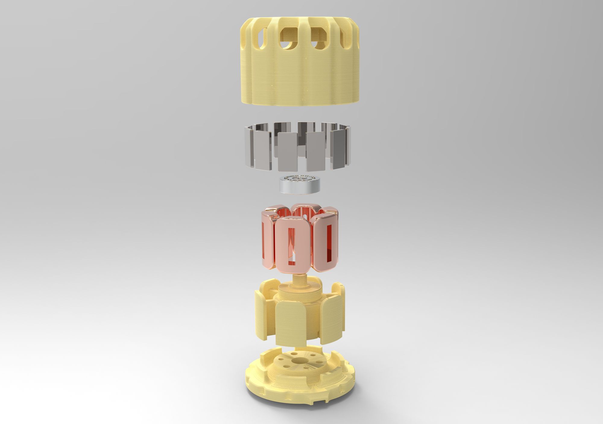
Here are a few renders of the final motor design that I decided on. The white/clear parts are printed in PLA while the base stator is made of PETG for the extra temperature resistance as the coils heat up.
Below is a draggable render where you can see the final explosion view of the design from multiple angles.
Here is an image of all of the different printed parts and hardware (aside from magnets and enamel wire) needed to assemble the motor.
These photos show a more in depth look at the design that I used in order to secure the bearing to the plastic piece. This has proved to work significantly better than the friction fit bearing mount seen in my first design.
Pictures of the parts I used to secure the bearing to the rotor and the stator
Finally here is an image of the final design assembled (again without magnets or coils) with a Sharpie for scale.
Last but not least, I thought I would throw in an image showing the amount of prototype parts it took to get the fitment of everything just perfect.
Assembly
Now that the printed parts are completed and they are successfully test fit I ordered the necessary magnets and wire needed to complete the motor and finally get it up and running.
The step-by-step plans for what the assembly will include are listed as below.
- Wind all 18 coils coils (0.65mm Enamel Wire)
- Measure coil resistance with University LCR meter
- Solder power leads and connectors to coils
- Assemble magnets into rotor (36x6x6mm Neodymium magnets)
- Create test stand to power and characterize properties of the motor
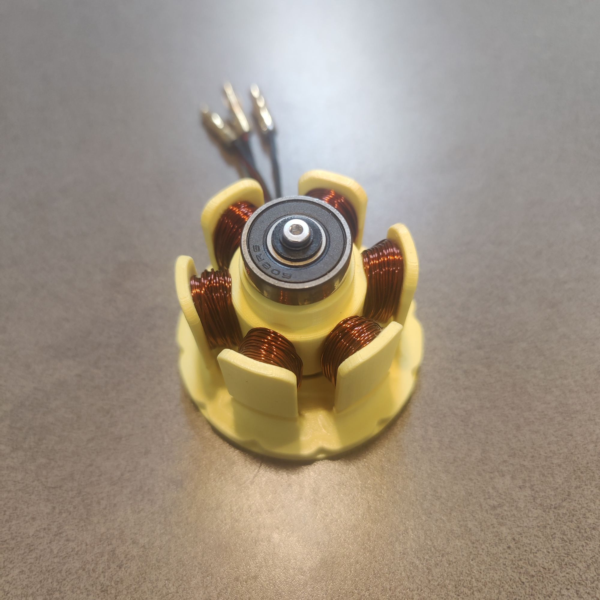
Here are the photos of the wound coils for the motor as well as the magnets in the rotor. I used a magnetometer app to find the northern pole of the magnets in order to properly construct the Halbach array.
Magnets in rotor (left), Would coils (right)
In order to make sure that I wound the coils correctly and the solder joints didn't induce any added resistance I took the stator assembly to one of the university LCR meters to measure resistance and inductance.
Labeled coils (left), LCR meter setup (right)
Below is a table summarizing the LCR measurements.
| AB | AC | BC | |
|---|---|---|---|
| Resistance (mOhms) | 699 | 705 | 708 |
| Inductance (uH) | 56.45 | 57.69 | 57.19 |
While coil A differed slightly I deemed this within my allotted margin of error and moved forward.
Finally once it was fully assembled I was able to hook everything up and hope that it would spin. Below is a video of its first spin.
Video of me spinning up the motor for the first time.
I would have liked to test the torque of the motor with a dynamometer but I did not have access to one at the time. Maybe I will save this for a future project but for now I'll have to leave this one here.
Conclusion
I really enjoyed this project because it was the first project I've done that required me to do a lot of research and get a baseline understanding of what was needed to complete the project before even starting.
This took quite a long time to make but I think it was ultimately worth it as I have vastly expanded my knowledge of motors and motor design and I actually was able to create a working motor. Hopefully I am able to carry the skills that I learned through this project onward to future ones.
Thanks for reading this post. If you are interested in any of my other posts they are linked below!
References
[1] T. Batzel, A. Skraba, and R. D. Massi, “Design and Test of an Ironless Axial
Flux Permanent Magnet Machine using Halbach Array,” IAJC-ISAM Joint
International Conference, vol. 88, 2014.
]]>This is a quick post about a small project that I made for the PRISUM Solar Car Club here at Iowa State.
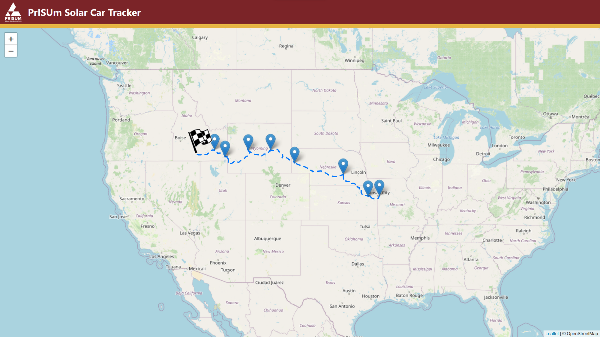
Every other summer our team competes in the American Solar Challenge.

This competition consists of both a track race as well as a 1300 mile road race across the US seen above. The track race (FSGP) which includes safety scrutineering of the car as well as the American Solar Challenge road race are both about a week long leading to a very long two week competition.
As I could only get one week off from my internship I chose to attend the American Solar Challenge which means that I would have to sit and anxiously wait for updates from the team and completely out of the loop to what was happening live.

I then realized that our car's telemetry system, which is cellularly linked and connected to the internet wherever the car goes, outputs the latitude and longitude of the car live every second through its log files.
The problem was that there wasn't any good way to display that data and as the competition drew near many of my friends and family began asking where they could follow the competition.
This gave me the idea to make this tracker webpage so anyone in the world could see the live position and speed of our car.
The main aspect of this project uses a project called Leaflet.

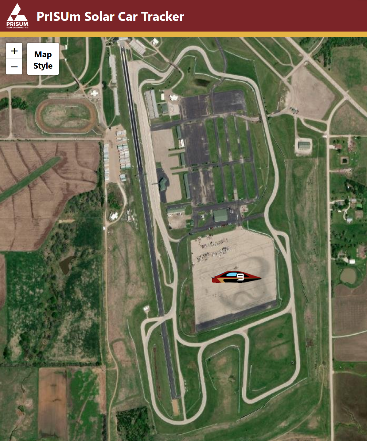
Leaflet is an open source project for implementing custom maps into websites without the need for embedds, iframes, or api keys. This seemed like the perfect use case for me and I began coding up the site.
Once I got the map readly and scaled correctly I made a basic theme with our team colors and used the official route data from the American Solar Challenge website in order to map a route along the map with checkpoints.
Next I had to handle the hard part which consisted of establishing a live connection to the car while keeping the webpage static which is needed for using Github pages.
I started this process by procrastinating the hard part and spending way to much time in Photoshop creating a clipart-esc sprite of our current solar car.

Finally I started on the live connection aspect and started implementing a websocket connection to the car. Unfortunately for me, our software team that made the telemetry page codes things extremely efficiently compressing all of the car's data output into illegible strings of bytes. While making the message size 20 times smaller this made rummaging through their code trying to understand it all 20 times harder.
In the end I was able to get the connection established to the car with my final bug-fix that got everything working being pushed to Github at 8:57am just three minutes before the competition started at 9:00.
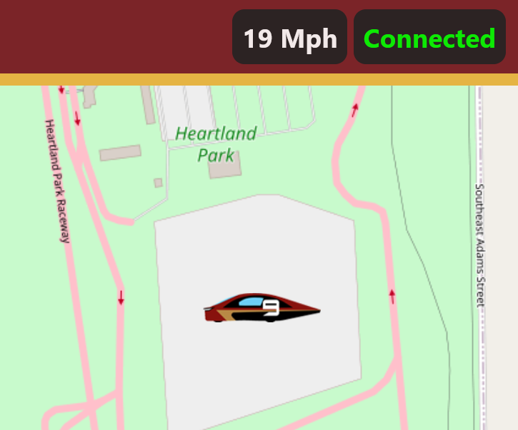
With the tracker up and running there were many current members and alumni of the team as well as friends and family that were able to see the current status of the car with the GPS even being accurate enough for you to be able to roughly see the racing line on the track race.
Over the next several days of the competition I had nothing better to do but to make even more updates to the tracker. The final iteration included a terrain view button, live connection and speed status, and changing the direction the solar car icon faced based on the movement of the actual car.
And with that the project was more or less complete and I headed off to take part in the American Solar Challenge which ended up being a great experience!
If anyone is interested, the live webpage for the solar car is below. Whenever we test drive the car around campus it should connect and update the position live.
Finally, if anyone wants to see my horrid coding skills barely holding this whole project together the source code from the site and the repository its hosted out of is linked below.
 CKraft11
Github repo for tracker site
This project was really fun to work on and I definitely learned a lot as coding projects are not something I often do. It was also really cool hearing from all the past alumni on the team, some of whom I've never met, talk about religiously stalking the page in an open tab at work for those two weeks.
]]>With my work in the Iowa State Solar Car club I have learned so many things about so many different technologies that I have not had the chance of working with before.
One of the things that has come to interest me the most are motors. Getting the chance to learn and tune the motors on our car has led me to develop a further interest in how they work.
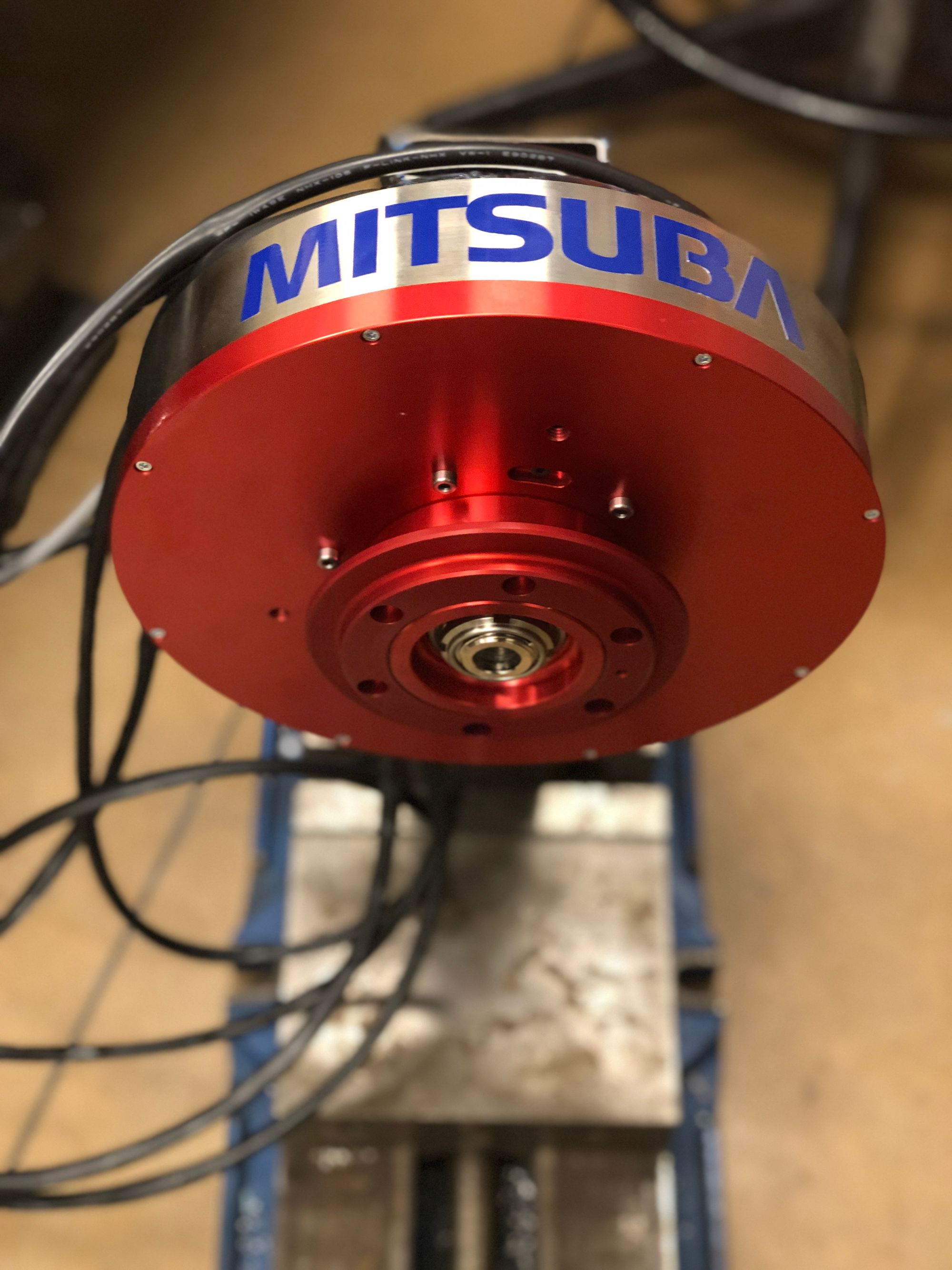
On our current car we use BLDC motors from Mitsuba in Japan directly driving our wheels inside the rims of our wheels.
With this urge to dive deeper and figure out how exactly brushless motors work I decided to try and design my own so I can experience every hurdle and roadblock and hopefully learn something from it.
Going into the design I just wanted to try my hand at making a motor without having to learn advanced motor simulation software like Ansys MotorCAD and Ansys Maxwell. My goal was simply to make a motor that works and spins on its own.
Starting a design in Autodesk Inventor, I began by creating the main profile of the stator.
I made this design using reference images I found online while adding features optimizing the design to be 3D printed. As seen above I also added slots on either side of the coil to make routing each coil and keeping it organized significantly easier while allowing all the wires to go into the center so the design can be screwed flush.
Continuing on the design I needed to create a solution for implementing a bearing. As I wanted to keep the costs down on the project I decided to use a standard open ball 608 skateboard bearing that I had lying around.
Finally I ordered some 2mm*10mm*20mm neodymium magnets off of AliExpress. I then culminated this into a final design using all of these parts.
Now it comes time to assemble the motor. I started researching different ways of winding the coils and different parameters in terms of coil winding and wire gauge that I could use to my advantage to increase the efficiency of the motor.
I started researching the differences between Wye and Delta winding configurations.
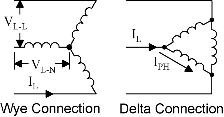
Although a Wye configuration on paper would be better suited for this motor design because of the reduced need of current to start spinning the motor. However, I chose to use the Delta configuration as it was significantly easier to wire given the design that I had.
This link below contains a lot of interesting information if you are interested in learning more about the differences in these two types of windings.

Although I could research and try to optimize the wire guage of the coil I already had a spool of 0.5mm enameled copper wire that I did not have plans to do anything with so I decided to use that.
I chose to use this wire with 60 windings across the all 6 poles of the motor in 3 individual phases.
Now that the wiring was done I needed to test the motors functionality. I hooked the motor up to an old ESC that I had from making drones and using a servo controller to manually control the RPM of the ESC. I found that the motor worked best around 14-15 volts but did not have a lot of torque output.
One thing I did notice was that I needed to flick the motor pretty hard in order for it to start spinning. This is probably due to many inefficiencies in the motor such as lacking an iron core for the electromagnet or the higher starting amperage needed for a Wye configuration.
Future Changes
Below I am going to sum up a few key takeaways that I have learned from this project and future ways I could remedy it in the next motor design that I make. I think the biggest faults in the current design are as listed below.
- Lack of iron core in the electromagnets
- Magnets are pretty weak and could be stronger
- Spacing between the coil and magnet significantly too high
- Using Delta wiring instead of Wye
Some ways that I could remedy this are by making an axial flux motor for my next design. This would allow for an extremely thin gap between the rotor and stator and because of the coil design of an axial flux motor I could also make a separate jig for more accurately winding each individual coil instead of winding around the stator all at once.
Since making this I have also learned more about motor theory and simulating motors through applications like Ansys MotorCAD and Maxwell through work that I have done at my internship at Husco Automotive.
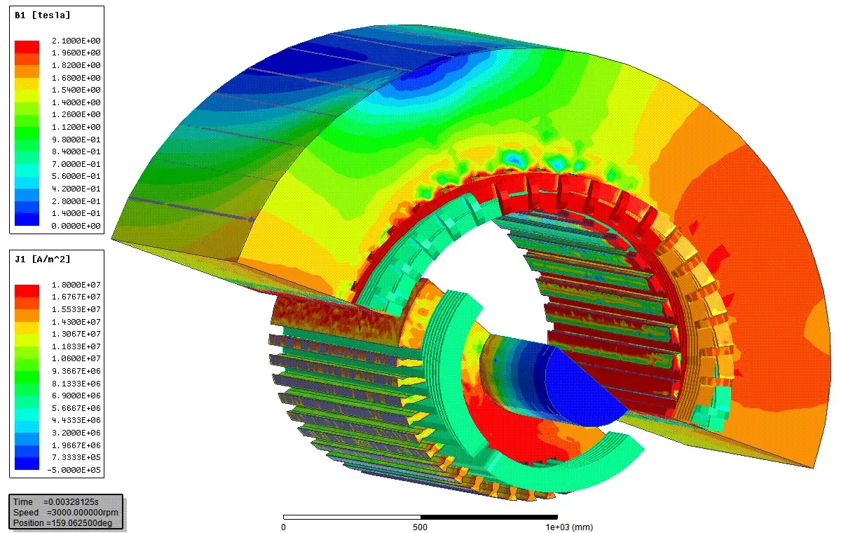
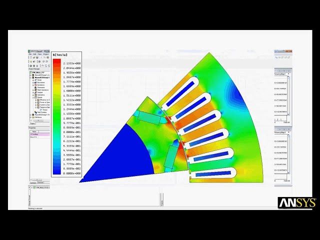
Examples of Ansys MotorCAD and Maxwell Being Used for Motor Design
Hopefully I will be able to utilize these skills in order to refine my next design to be more efficient and quantitatively thought out.
Stay tuned for that to come!
]]>At Iowa State University, one of my main interests has quickly become the PRISUM Solar Car Club. It has given me an opportunity to use my engineering skills outside of classes with some pretty cool people.
As I am a Freshman at Iowa State, and at the time of writing P15 is coming to the end of its build cycle, most of the core systems in the car have already been set in stone. However there are a few smaller projects that haven't been tackled yet.
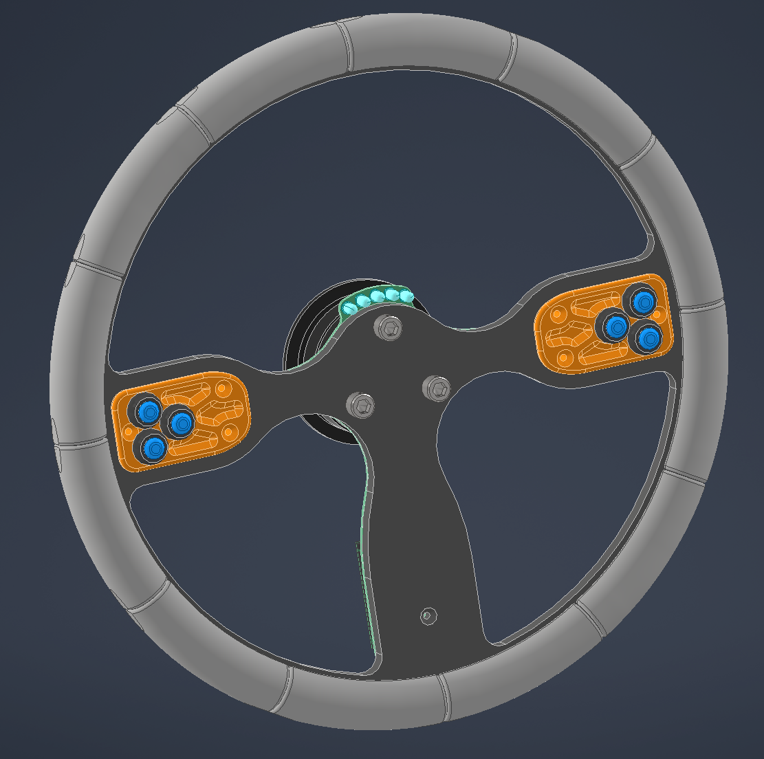
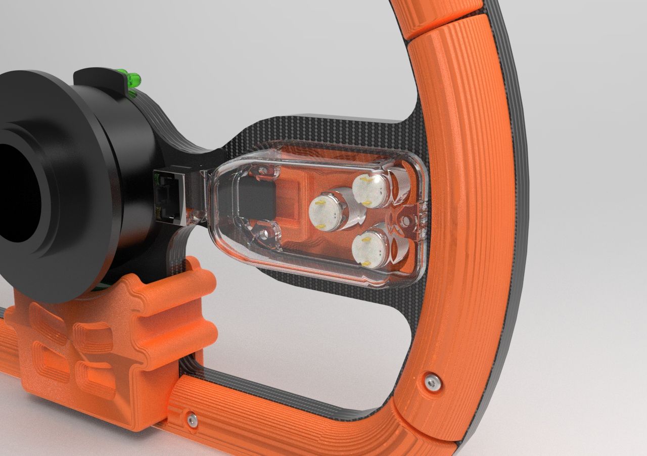
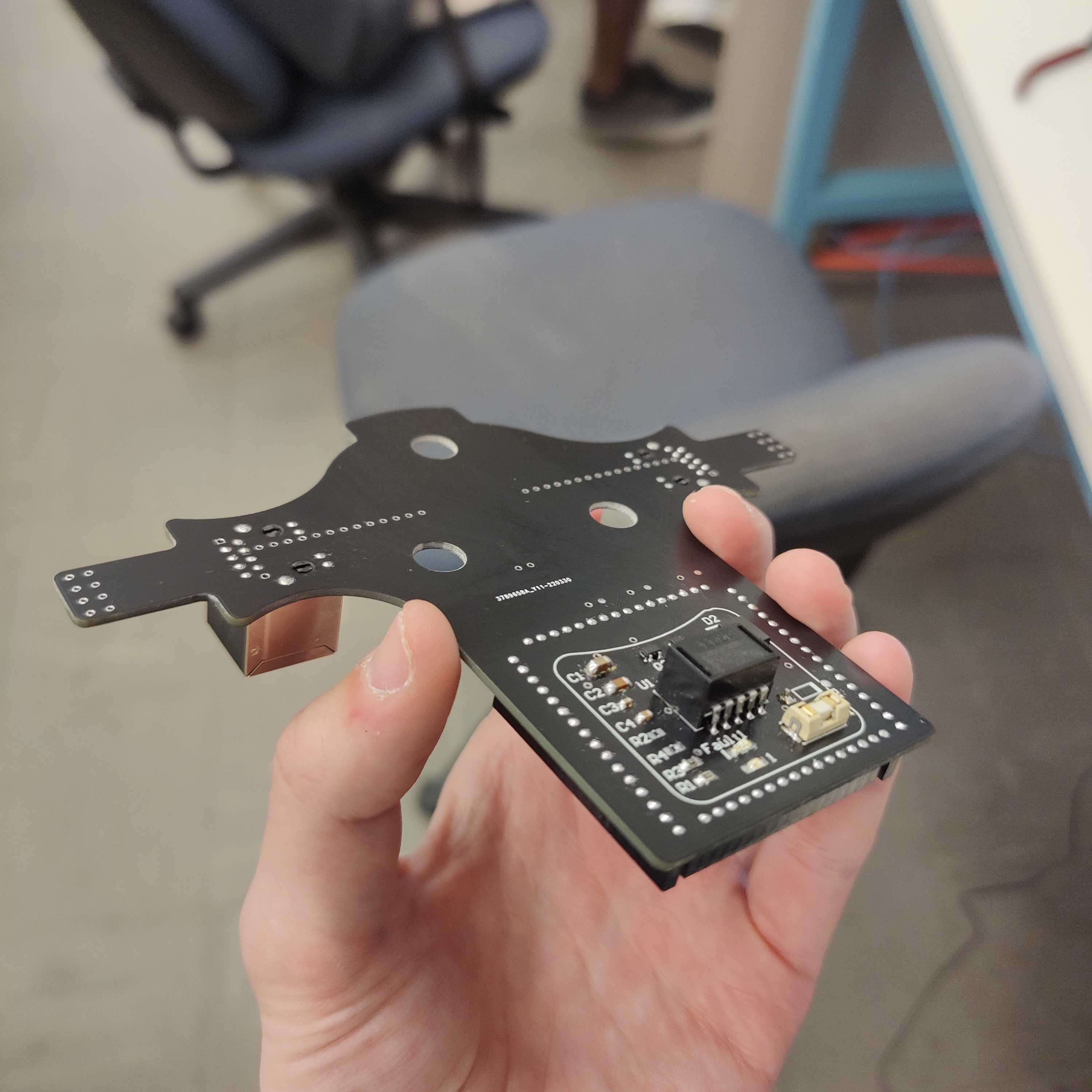
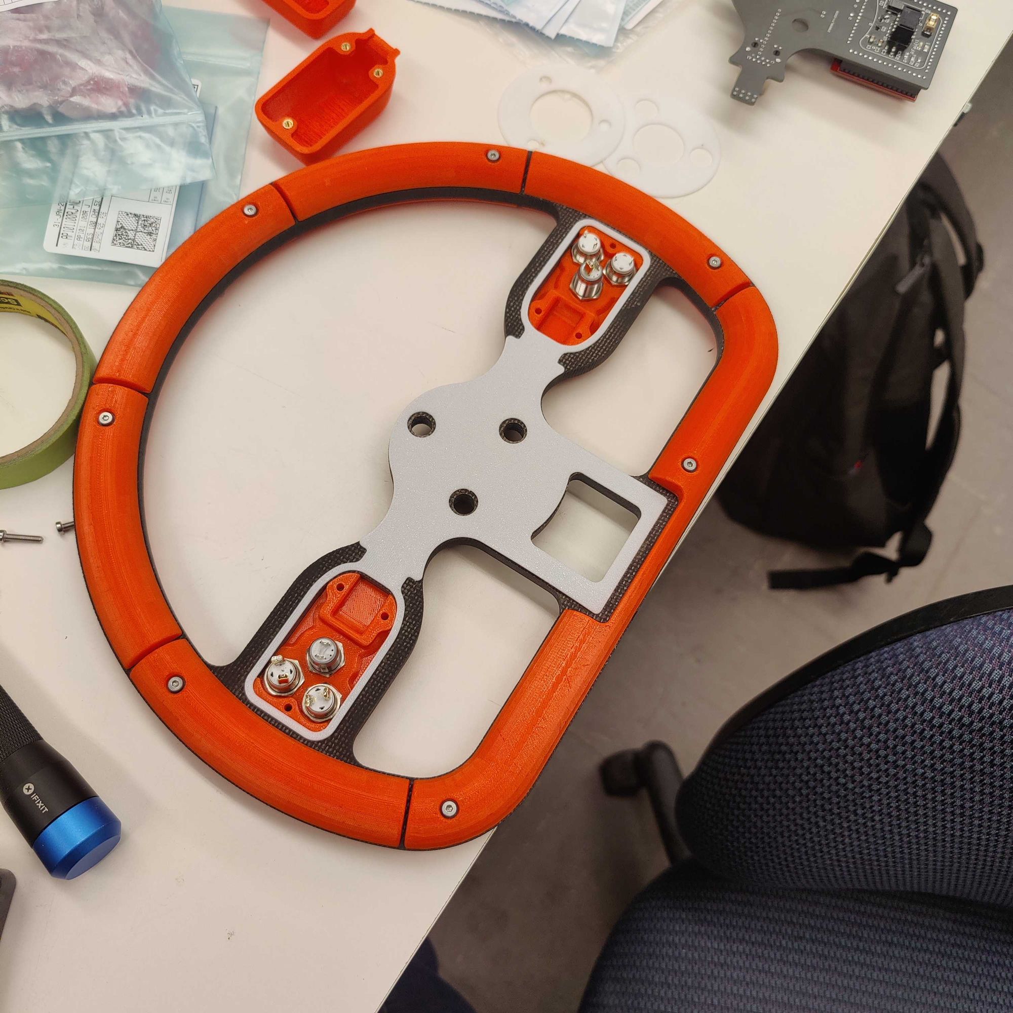
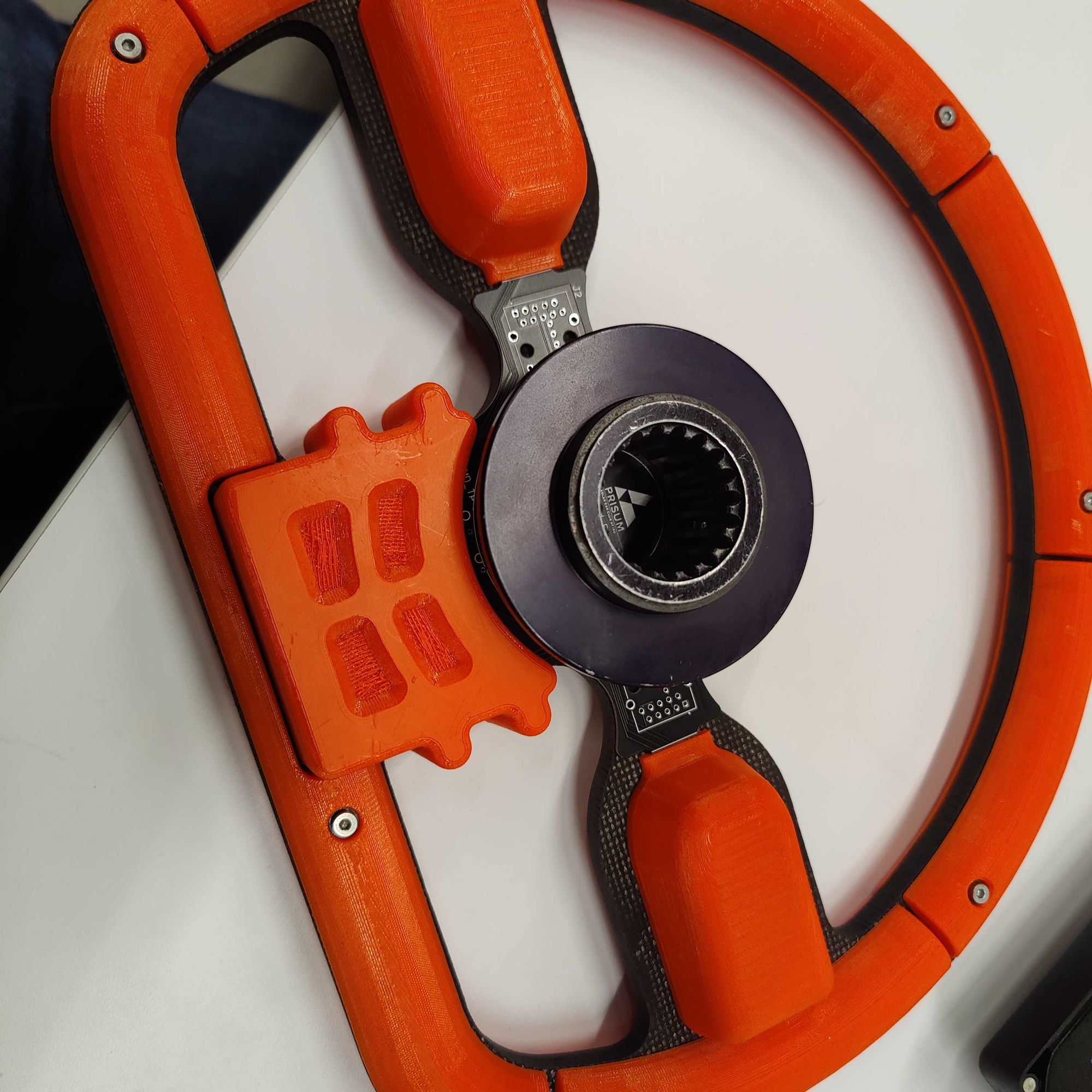
One of these projects is redesigning the steering wheel. The current steering wheel in the car has given us many problems that have greatly inhibited our ability to drive reliability without breaking down. Looking at the image of the disassembled current steering wheel below you can see that it mostly consists of a waterjet sheet of carbon fiber with holes drilled for the quick disconnect fitting and the buttons used for turn signals, hazards, etc.
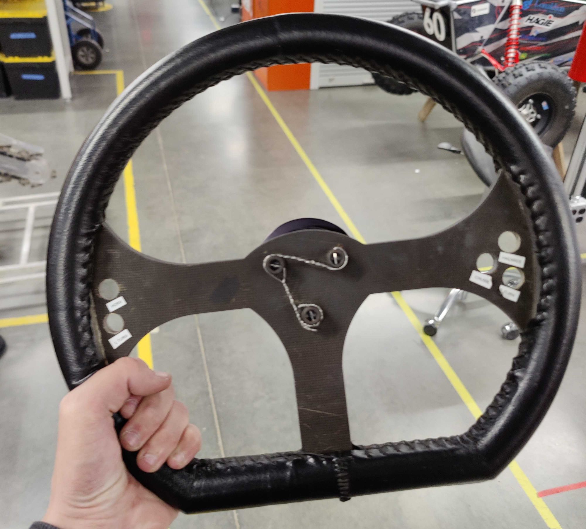
The problem with this design is that the wires that connect to the buttons to the aptly named buttonboard PCB that controls them, get individually routed to buttonboard deeper into the car. This means that when rotating the steering wheel, as there are more than 15 individual wires being rotated, over time some either develop a loose connection or snap off entirely.
As the steering wheel controls everything from turn signals to our regenerative braking we cannot have these faults inhibit us from driving at race this summer.
Some other smaller issues with this design are that as the holes for the buttons are drilled, the number of them and their positions are fixed and can only be redone by re-waterjetting the main carbon panel which can cost up to $50 in materials and machine time. The hole pattern was also drilled by hand with no CAD available which makes creating a strain relief component that integrates with the current design quite challenging.
Taking all this in mind I started on defining the requirements I was going to set for myself for the new design to meet.
- Integrate the buttonboard PCB into the steering wheel itself
- Limit the connection from the steering wheel to the car to a single wire
- Provide the ability for the button position and count to be quickly redesigned if needed
- Utilize 3D printed parts as much as possible and mechanical fasteners over adhesives
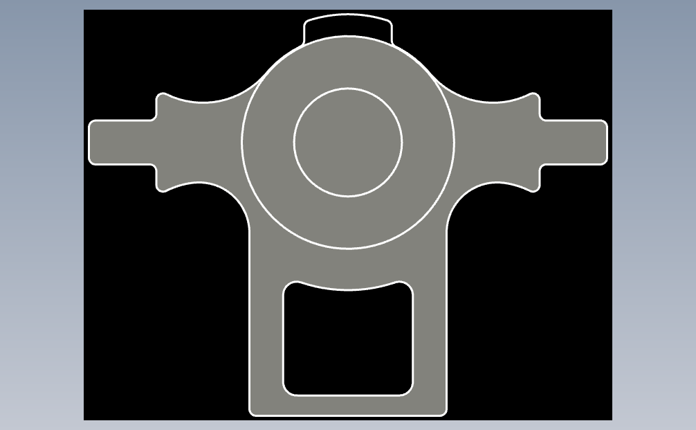
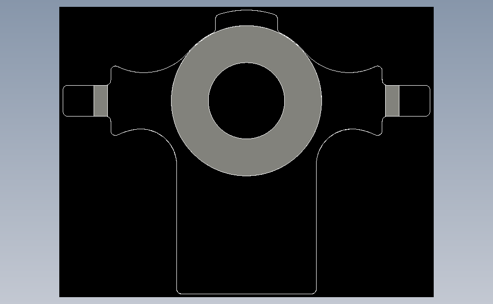
With these in mind I started to design the steering wheel. I jumped into Inventor and started modeling and after a few hours was left with my first iteration.
Various views of the first iteration steering wheel design
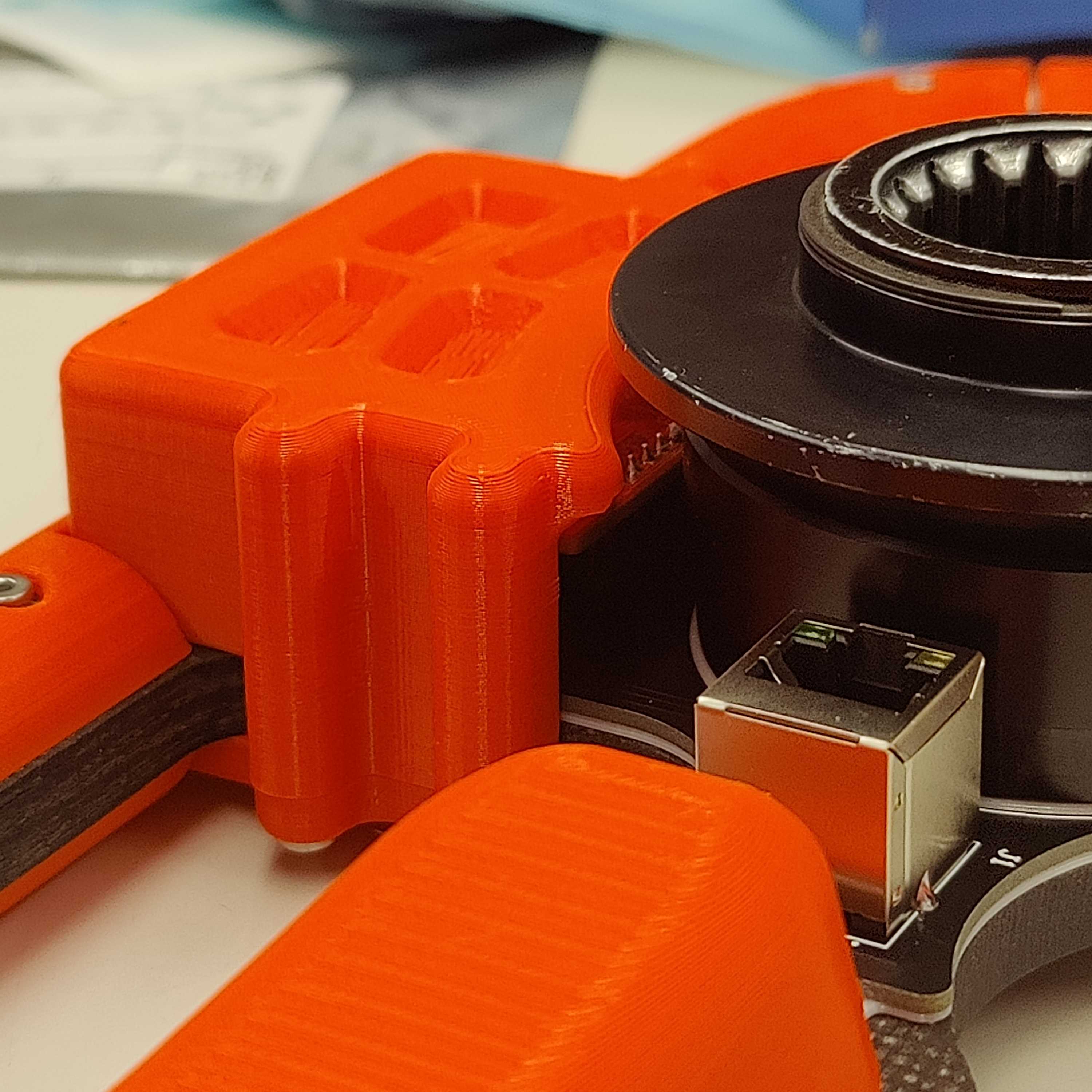
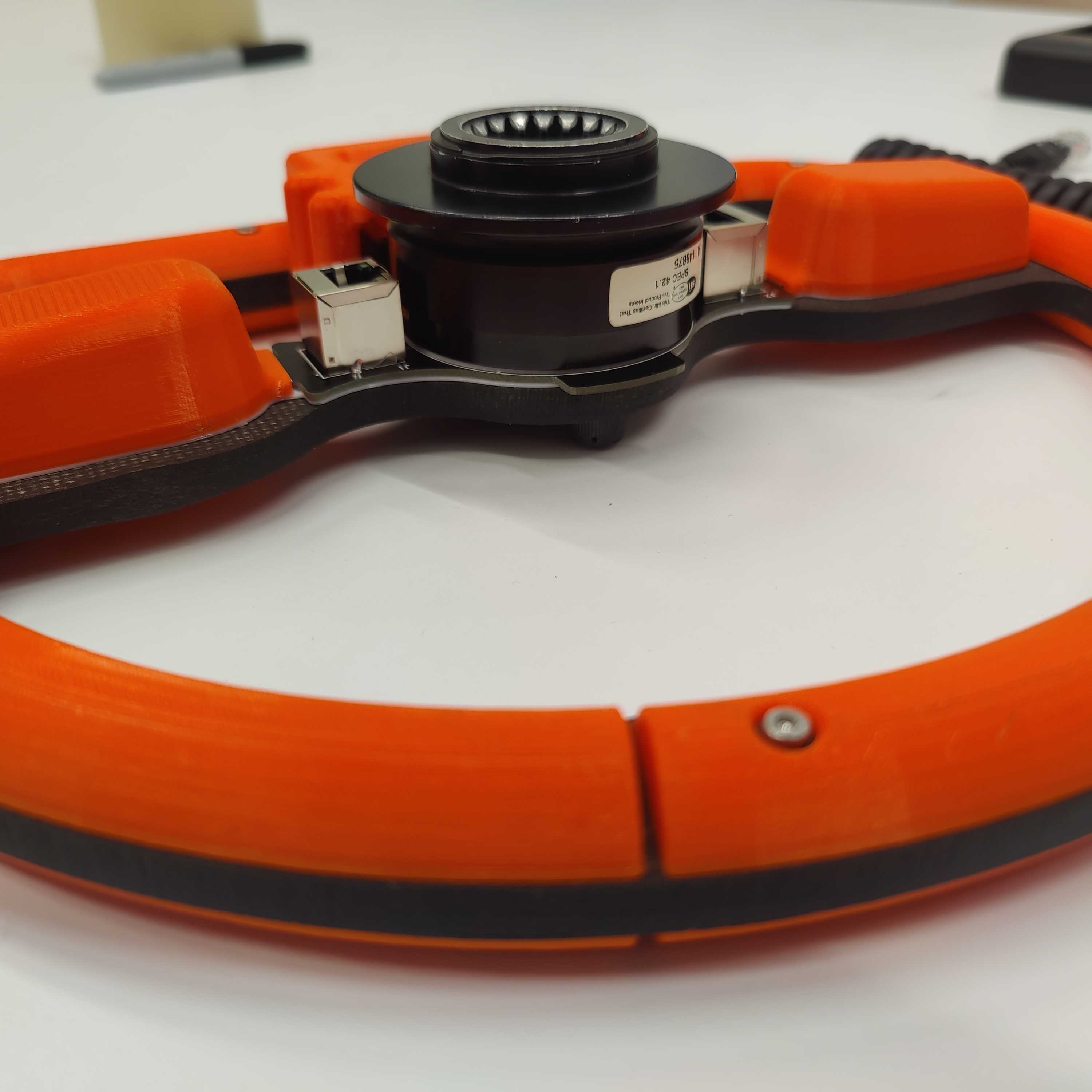
As seen above, there are many aspects to the new design including the integration of the buttonboard PCB shown as a placeholder in green, with the smaller PCB being the compute module needed to run the code. There are also 3D printed redesignable inserts for the buttons combined with an RJ45 Ethernet jack used in order to transmit power and CAN data from buttonboard to the rest of the car.
I showed this design to the team and received a lot of really helpful feedback. The core areas of feedback are as follows.
- This design is larger than the current one and takes up more space in the solar car. Some drivers noted that the current one already got in the way often
- Much of the PCB and compute module are unprotected which could lead to damage from it being handled so much
- PCB shape and size could lead to increased manufacturing cost from the PCB fabricator
- Add some sort of gasket between the PCB and carbon panel
With this feedback I embarked on creating a second more compact and integrated design that could also fufill the new requirements of smaller size as well as protecting and optimizing the shape of the PCB.
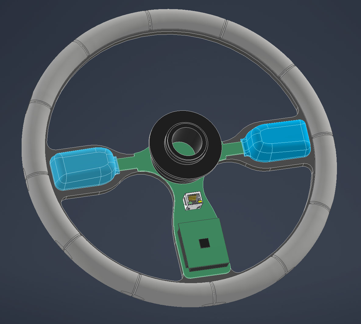
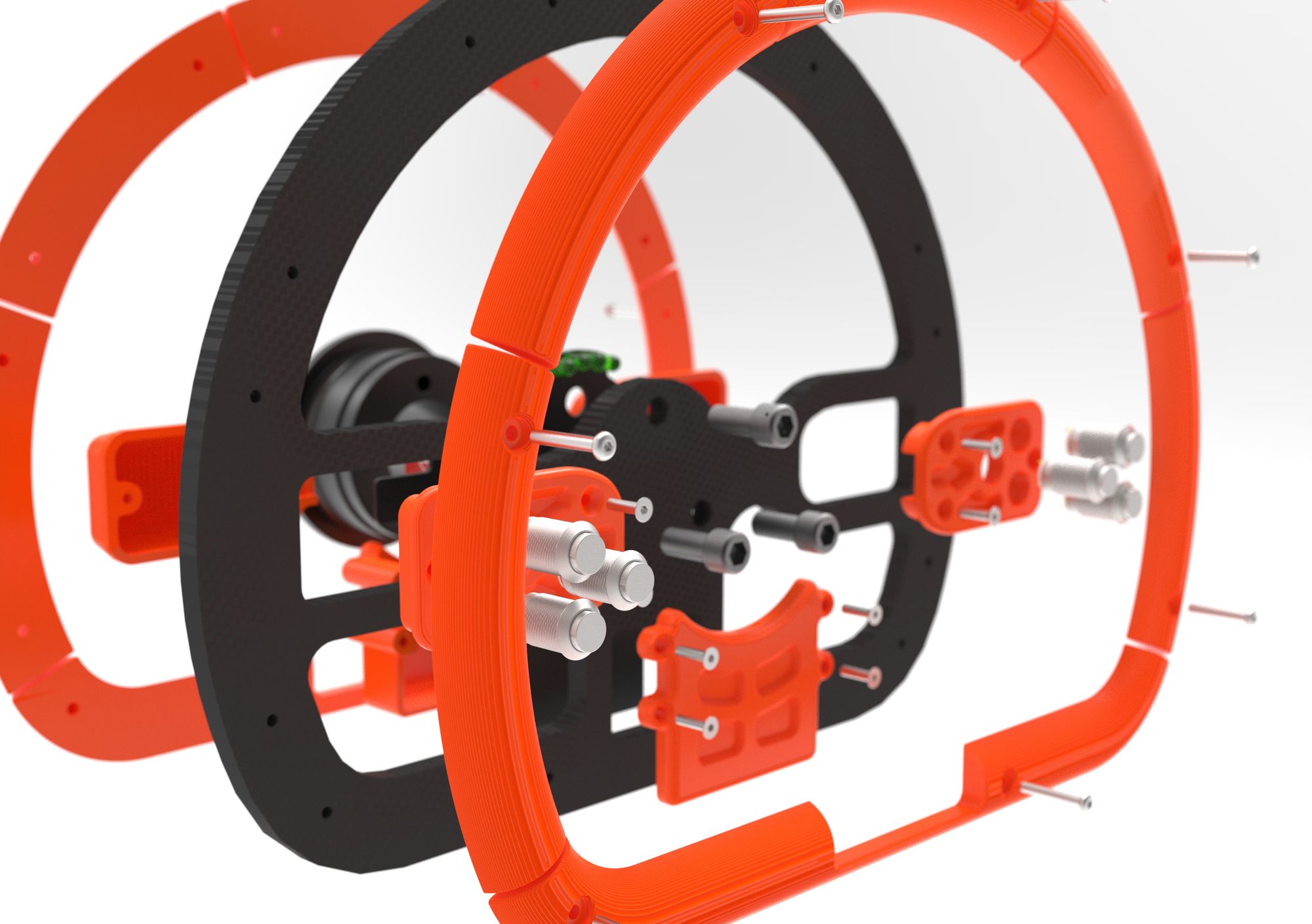
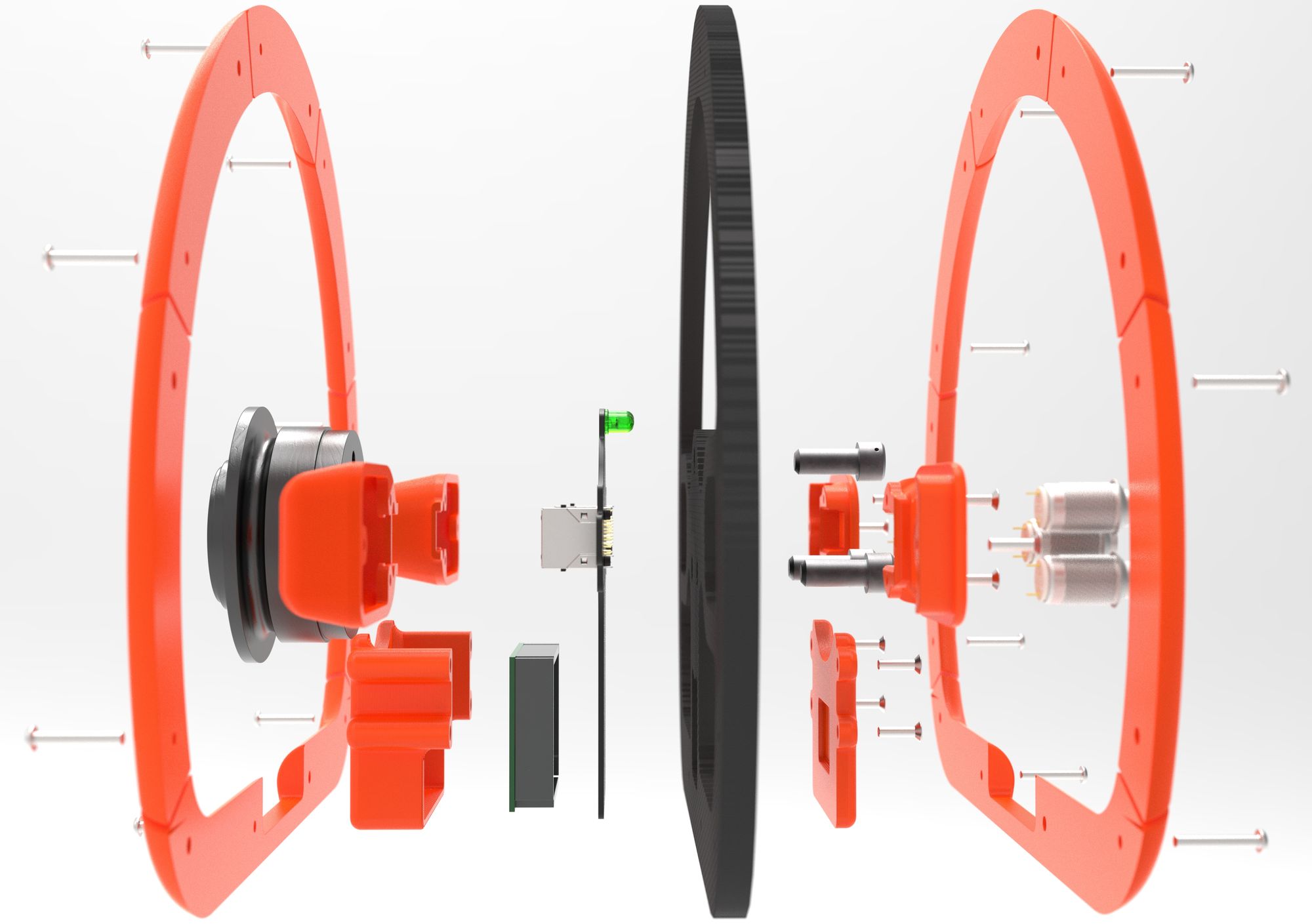
I culminated this all into a brand new design to which a draggable view of it is seen below.
This new design includes numerous improvements from the first namely being, compact size and increased protection around the PCB and exposed electronics. It also has 2 RJ45 connectors in case one fails.
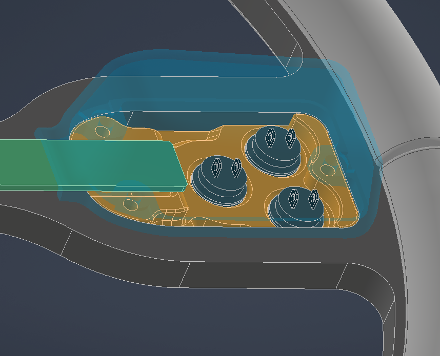
Seen below are areas on the new design with increased protection around the electronics.
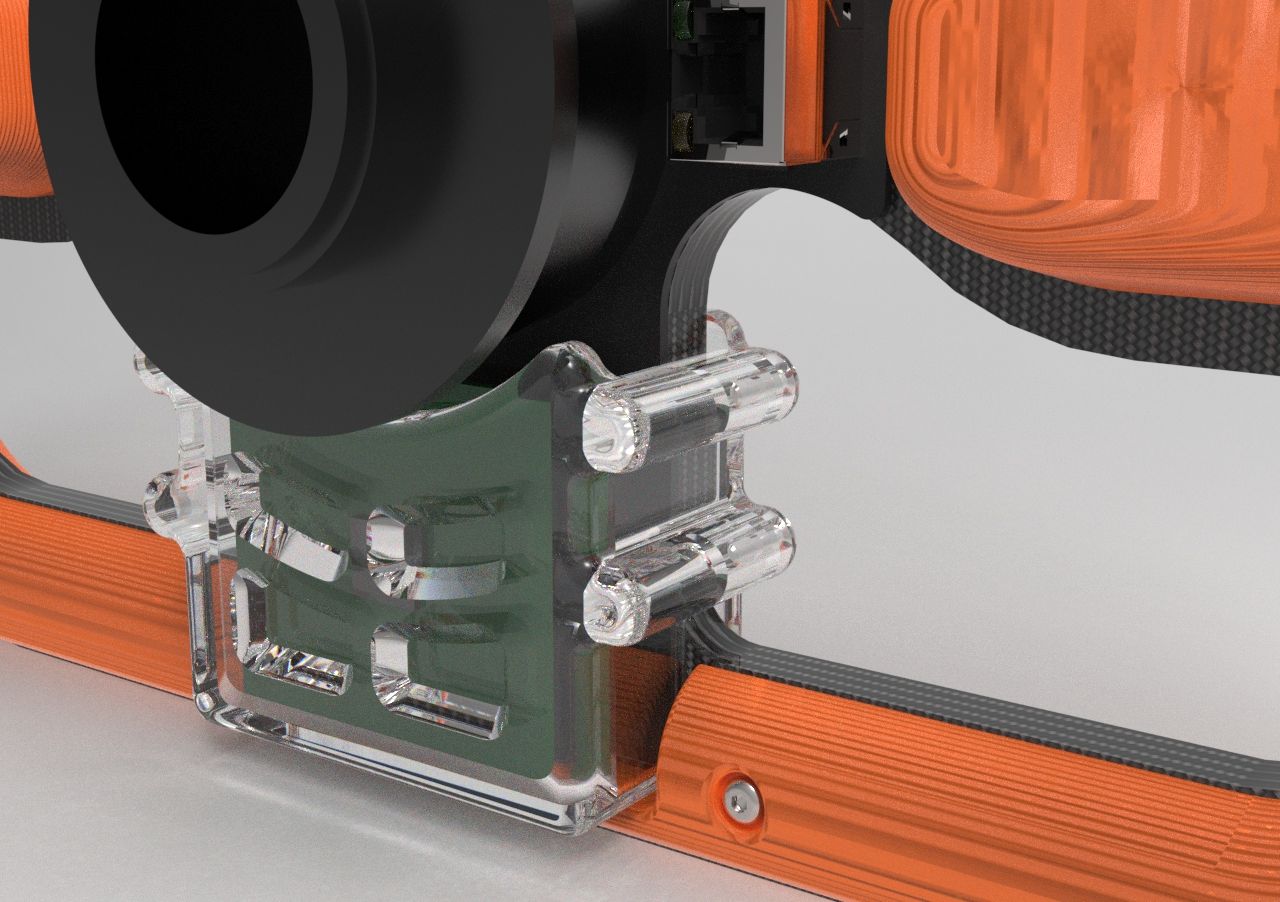
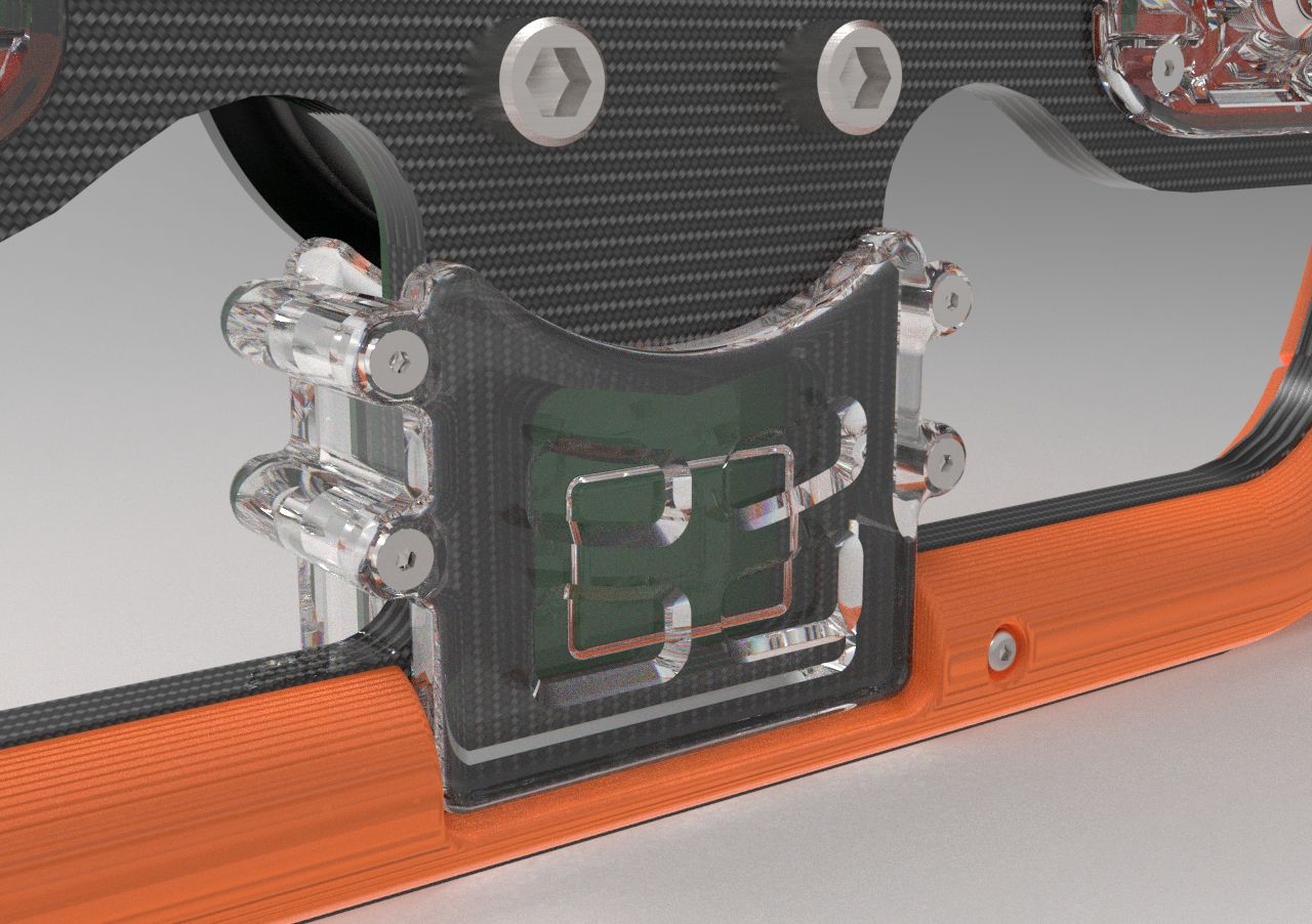
Compute Module Cover (left), Button/Wire Cover (center), Front Component Cover(right)
After showing this design to the team nobody had issues to raise on the second iteration so I began working with the electronics team to develop the new buttonboard PCB meeting the form factor of my new design.
I started off by exporting the outline of the PCB placeholder I created in Inventor and opened it up into Adobe Illustrator where I marked areas where electronic components could not be placed as the PCB would be directly against another part.
Outlines of PCB part placement
These outlines could then be imported into Altium Designer, our teams' PCB designer. Members of the electrical team were then able to convert this into a PCB board outline and start the process of creating a board schematic and placing components.
Here is the finished design that they came up with below.
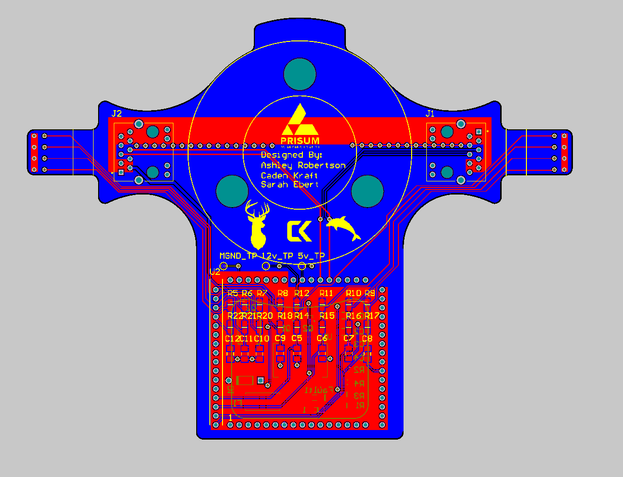
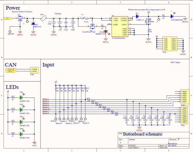
buttonboard PCB layout (left), buttonboard schematic (right)
With this step complete we were able to order the PCB and its components and I was able to start manufacturing the mechanical parts needed for assembly.
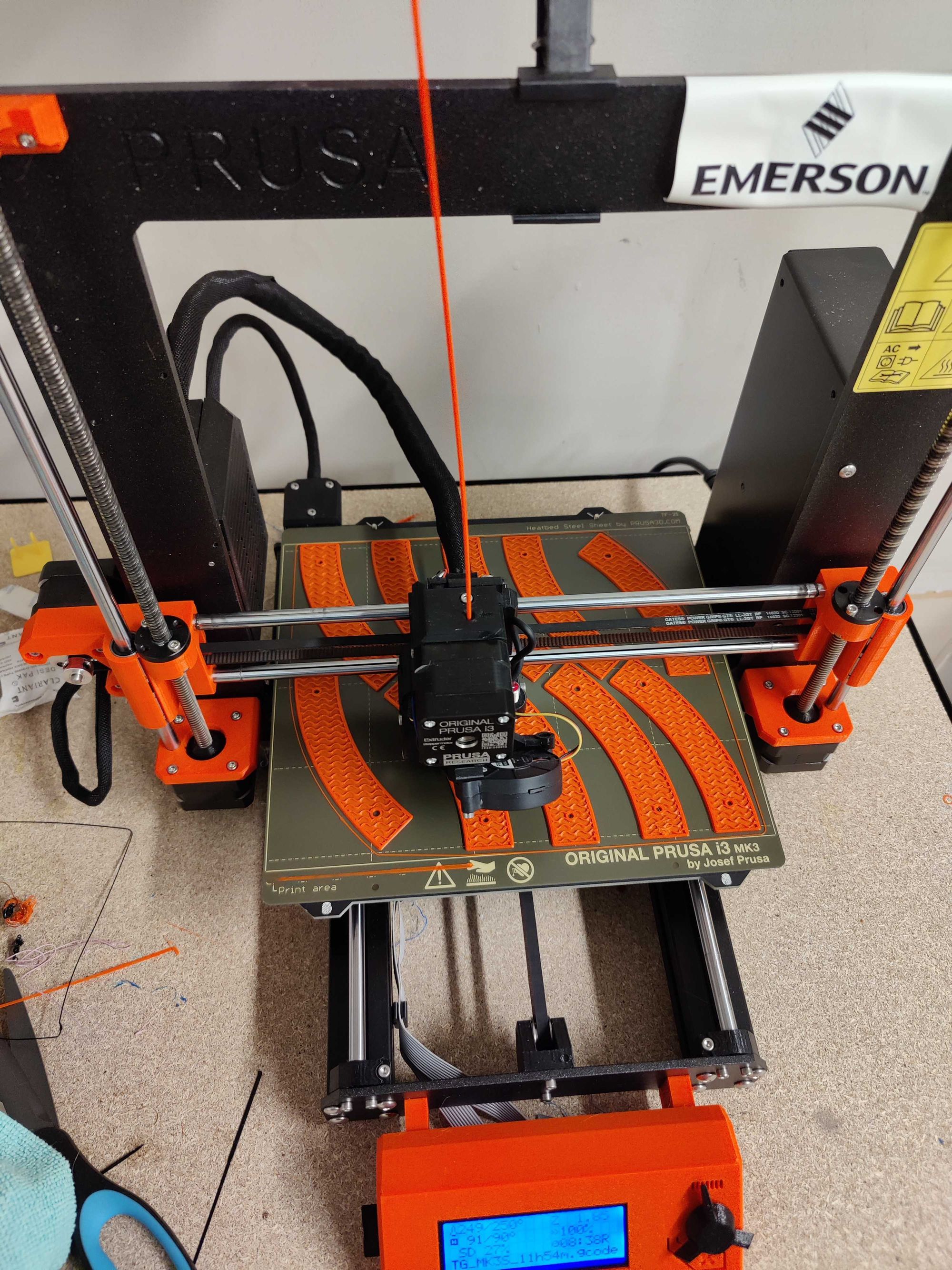
While the center peice was again waterjet out of the same carbon material of the first, most of the components were 3D printed using the 3D Printing Club's print lab in Prusa3D PETG plastic to provide temperature resistance during the hot summer temperatures they will endure.
Once all the parts were printed and the carbon plate was waterjet I soldered and tested the components onto the brand new buttonboard PCB.
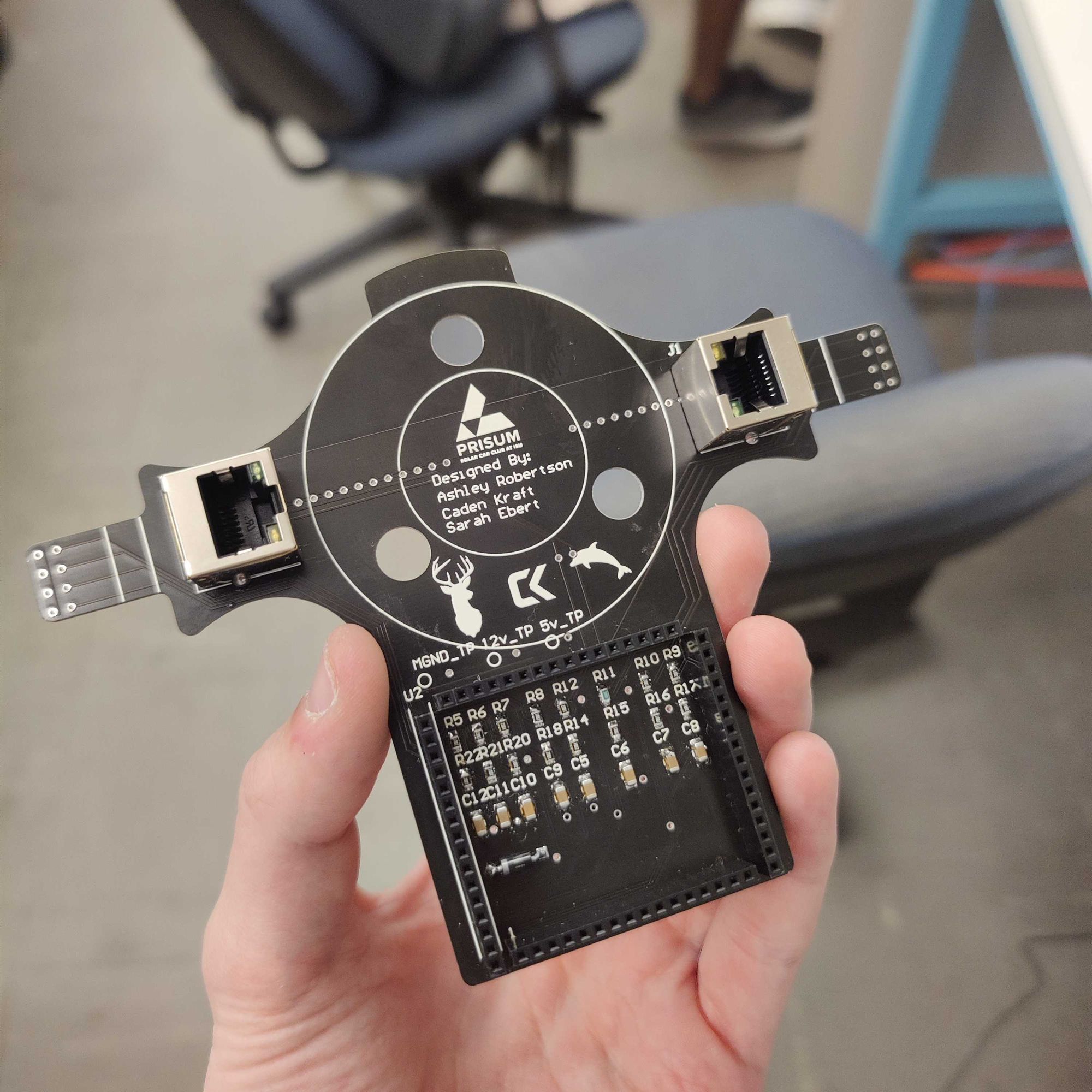
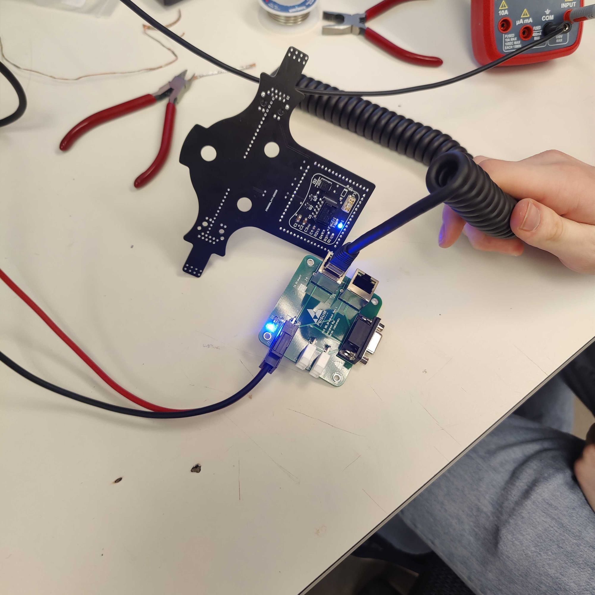
Soldered buttonboard PCB (left, center), Buttonboard testing (right)
Finally, all the parts were ready to assemble. Here are some images documenting the assembly of the finished product.
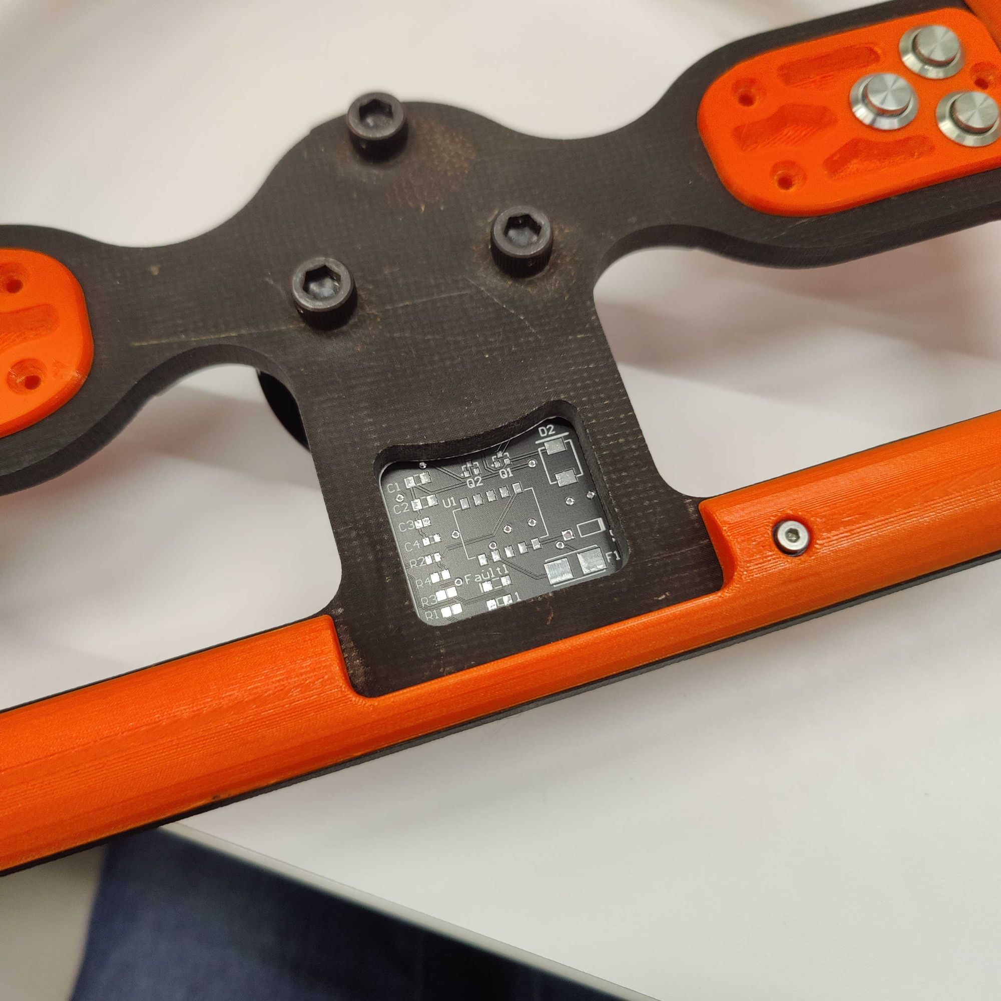
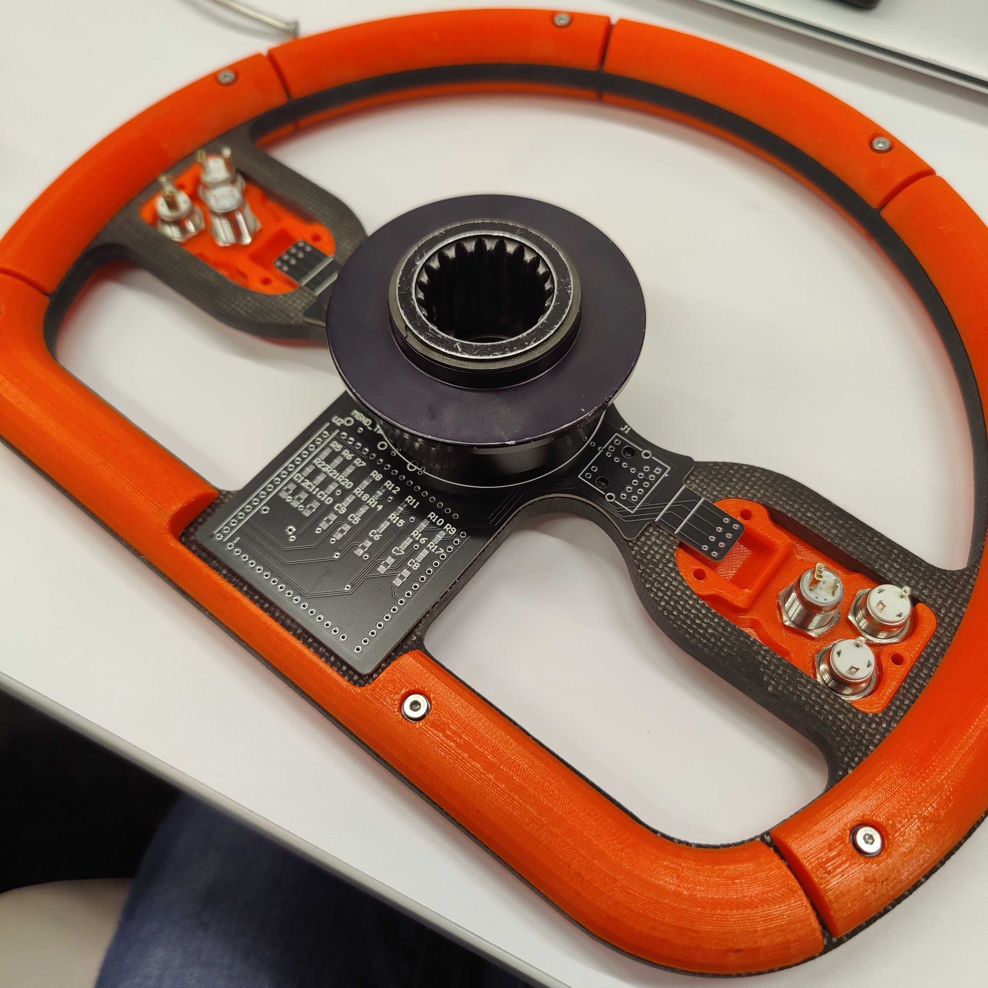
Front PCB area (left), Wheel assembled without back covers (center), 3D printed rubber protection gasket (right)
And with that the project was more or less complete. The software team was able to make a few adjustments to their code and it was connected to the car and ready to go in no time.
Over the course of the past few weeks the steering wheel has been working great while driving and has presented no issues so far and seems to have solved the ones of the previous design.
I really enjoyed making this project as allowed me to learn a lot more about the solar car club and meet more people on the team. I think the final product turned out really well and bears a striking resemblance to the CAD used to create it. Hopefully it will be able to stand up to the intense rigor of the 1300 mile American Solar Challenge this summer!
]]>
When I began my search to find the best blog/CMS that I could host at home (or in my dorm room) on my server, I landed on Ghost pretty quickly with its slick UI and broad feature-set including an admin panel, app integrations, and native Docker support.
My problems arose when it came to hosting. Although I can host it on my server I currently cannot port-forward traffic to my blog, and it also introduces a pretty significant security risk.
Bring in GitHub pages. GitHub pages is a great way to host websites completely for free with the one caveat being that they have to be completely static. As Ghost doesn't natively support this to my knowledge, this is where the guide begins.
Requirements
- Server/Laptop/PC you have to host the server on for local editing. The final site will be on GitHub pages so this machine doesn't have to be running 24/7.
- Free GitHub account
- Basic Linux command line knowledge
- Patience
Setting up Linux environment
This guide should work natively on Linux and macOS (untested) and if you only have a Windows machine, it also works using WSL2.
First, we need to install Docker and some other packages. Going forward, I will be listing commands that would be used on Debian/Ubuntu-based systems as that is what I personally used, but they should be similar for other platforms. To install Docker, we can run these commands below.
sudo apt-get install ca-certificates gnupg lsb-release nano git wget curl imagemagick optipng pngcrush jpegoptimDownload general packages and image optimization
curl -fsSL https://download.docker.com/linux/ubuntu/gpg | sudo gpg --dearmor -o /usr/share/keyrings/docker-archive-keyring.gpgAdd Docker GPG key
echo \
  "deb [arch=$(dpkg --print-architecture) signed-by=/usr/share/keyrings/docker-archive-keyring.gpg] https://download.docker.com/linux/ubuntu \
  $(lsb_release -cs) stable" | sudo tee /etc/apt/sources.list.d/docker.list > /dev/null
Set up stable repository
sudo apt-get update
sudo apt-get install docker-ce docker-ce-cli docker-compose containerd.io
Next, we want to install all of the packages needed for the static site generator that we will be running outside of the Docker container on bare metal.
sudo apt-get install python3 python3-pip wgetDownload Python 3 and pip
Setting up the Ghost Docker container
The method I'm going to be using to set up Ghost with Docker is through docker-compose. Firstly we need to create a docker-compose.yml file.
nano docker-compose.yamlIn nano paste and edit the docker-compose install parameters below.
Optionally you can mount the folders from within your docker container to somewhere on your local machine which can make development much easier. If you would like to do that add a volumes: section under the environment: section on both the ghost and db containers. If you are running Ghost on a remote server make sure to change url: from http://localhost:2368 to http://SERVERIP:2368. If you don't want to deal with any volumes you can delete both sections entirely.
You also need to know your PUID and PGID of your user account. Run the following commands to determine those values and then add those to the file below.
id -u # returns PUID

id -g # returns PGID
Get your PUID and PGID
version: '3.1'

services:

  ghost:
    image: ghost:latest
    restart: always
    ports:
      - 2368:2368
    environment:
      # see https://ghost.org/docs/config/#configuration-options
      database__client: mysql
      database__connection__host: db
      database__connection__user: root
      database__connection__password: EXAMPLE
      database__connection__database: ghost
      PUID: 1000 # change these to your linux account with "id -u" and "id -g"
      PGID: 100
      url: http://localhost:2368
      #NODE_ENV: development
    volumes: # allows you to easier develop and transfer files in and out of your website
      - /PATH/ON/LOCAL/MACHINE/ghost/content:/var/lib/ghost/content

  db:
    image: mysql:8.0
    restart: always
    environment:
      MYSQL_ROOT_PASSWORD: EXAMPLE
      MYSQL_DATABASE: ghost
      PUID: 1000 # change these to your linux account with "id -u" and "id -g"
      PGID: 100
    volumes: # allows you to easier develop backup/manage your database
      - /PATH/ON/LOCAL/MACHINE/ghost/mysql:/var/lib/mysql
docker-compose.yml
Press Ctrl-X to exit and Y to save your changes. Before we start the container, we also want to add your current user to the Docker group on your computer so you will be able to run all of these commands without using sudo.
sudo groupadd dockerCreate the Docker group
sudo usermod -aG docker $USERAdd the current user to the Docker group
You will likely have to log out and log in for these changes to be implemented.
Finally, we can get into actually starting up the Ghost blog. If you are not running this on a server and are on a laptop or desktop, I recommend using VSCode with the Docker extension. The workflow is very nice for managing Docker containers and images.

Now we need to load up the Docker container we created earlier. Navigate to the directory that you created the docker-compose.yml file in and run
docker-compose up -dThis should take a while as it has to download and set up the Ghost Docker image but after it says the website is finished loading you should be able to navigate in your browser to http://localhost:2368 or http://serverip:2368 depending on your setup. You should see a nice-looking blog template with all the images loaded properly. Then you can add /ghost to the end of your URL to access the admin dashboard.

Here it will prompt you to set up an account and parts of your blog. I'm not going to go too much more in-depth on that side of things as that is more up to the user but if you have everything up to here working we should be good to set up the GitHub pages integration.
Setting up GitHub Pages
Now that we have our local Ghost blog up and running, we want to configure a static site to be generated and sent to GitHub Pages. To do this I made a simple python script that you can use to scrape your local site and push it to GitHub.
CKraft11Here we are going to create a folder to store your blog, download my script and the requirements file, and initialize a git repository.
mkdir ghost
cd ghost/
wget https://github.com/CKraft11/ghost-static-blog/blob/main/ghost_static_generator.py
git init
Next we need to set up a python virtual environment and install the dependencies for my script.
python3 -m venv ghost-static-env
source ghost-static-env/bin/activate
pip install pillow-avif-plugin requests beautifulsoup4 pillow gitpython
Then we have to go online to Github and create a few things. Starting with the repository, create a repository with any name you like and copy the URL under the "code" drop-down.
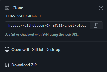
We want to add this repository as a remote repository location for git to push the files. We can do this by running
git remote add origin https://github.com/yourlinkhere.gitWe need to go back to GitHub and generate a personal access token that my script can use when creating the site to push files to your repo. Go to this link here and create a new token with a name of your choice and give it repo permissions. Copy this link and keep it somewhere safe (e.g., not in your git repository folder). Next, we can run the following commands to test everything working.
touch test
git add .
git commit -m "first commit"
git push -u origin master
git config --global credential.helper store
When prompted for a username and password, use the token created earlier in place of your password.
You should see a test file in your GitHub repo and a commit message if all has gone well.
Set up Scraper Script with GitHub
Lastly, we need to set up a script to update GitHub with the latest version of the blog. Luckily, I have made a script for this which we downloaded earlier.
Be sure to change these variables in the main function with those that you're using.
if __name__ == "__main__":
    parser = argparse.ArgumentParser(description="Generate static site from Ghost blog")
    parser.add_argument("--force-reconvert", action="store_true", help="Force reconversion of all images")
    args = parser.parse_args()

    source_url = "http://localhost:2368"  # Change this to your local Ghost URL
    target_url = "https://cadenkraft.com"  # Change this to your target URL
    repo_path = "/home/ghost-static-site-gen"  # Change this to your local repo path

    generator = ImprovedGhostStaticGenerator(source_url, target_url, repo_path, force_reconvert=args.force_reconvert)
    generator.run()
Open ghost_static_generator.py and change those three variables
To run the script simply run the command below. Due to the image optimization that I've implemented the first commit might take a while if you already have context on the site as all the images need to be converted. This is the command you run whenever you want to push an update from your website.
source ghost-static-env/bin/activate # Every new session you will have to run this.
python3 ghost_static_generator.py
Run python script to scrape and push changes.
Image Optimization
This script has pretty robust image optimization as that is something that ghost doesn't do too well at in my opinion. My solution is a bit overkill but should make your site load the fastest on the widest range of browsers. For every image that you upload my script will create a JXL, AVIF, and WEBP, and prioritize them as such based on what the user's browser supports.
Conclusion
If all of this went successfully, you should have many files in your GitHub repo now. To set up GitHub pages, go to the GitHub pages tab in settings and select the master branch. You can set up a custom domain here as well. Just make sure it is the one you have been using in these scripts. You can then go into the GitHub actions tab and open the static.yml file for the default "Deploy static content to Pages" action. Under actions you can change your upload repository from the root directory to the public folder created by the script.
jobs:
  # Single deploy job since we're just deploying
  deploy:
    environment:
      name: github-pages
      url: ${{ steps.deployment.outputs.page_url }}
    runs-on: ubuntu-latest
    steps:
      - name: Checkout
        uses: actions/checkout@v4
      - name: Setup Pages
        uses: actions/configure-pages@v5
      - name: Upload artifact
        uses: actions/upload-pages-artifact@v3
        with:
          # Upload entire repository
          path: 'public/.' # Change this line
      - name: Deploy to GitHub Pages
        id: deployment
        uses: actions/deploy-pages@v4
Paste the following code into nano and change the URL and SERVERIP variables at the top
If your page is bugged out and only showing HTML elements and no CSS or Javascript, you likely put the wrong domain in the script above. If you don't have a custom domain, the default should be https://username.github.io/. Also if GitHub pages doesn't work for you, Cloudflare pages also works using this same GitHub repo with zero change to your code. If all of this has worked up till now, congratulations, you're done! I hope this guide helped get you to that point.
]]>My Raspberry Pi's are some of my favorite devices that I own. Their versatility cost and ease of use have allowed me to implement them into a wide range of projects and learn a lot about computing.
One area I had never ventured however was the idea of clustered computing. Making a compute cluster out of Raspberry Pi's had always seemed like a popular project that people do but I personally had never seen a use for one.

However, after watching some videos by Jeff Geerling I was interested. Luckily enough I just so happened to have 4 Raspberry Pi 3b+'s that currently had no use. After doing some research the consensus came to be that Pi 4's are recommended for making clusters and 3's might be a bit slow but I'm mostly doing it as a learning experience as opposed to a necessity.
Looking at the designs people have made previously for Raspberry Pi clusters I was disappointed to see that the actual mechanical design of the enclosures/lack-thereof was quite lacking in my opinion so I wanted to make my own. I tasked myself with designing a new enclosure satisfying these requirements.
- Tool-less install of the Raspberry Pi's
- Streamlined power delivery (No big micro-USB cables)
- 3D printable with as few parts as possible
- Integrated network switch and active cooling
Here is the final design that I came up with. The view below is draggable to see the full model.
The center black component is designed to be 3D printed without supports with integrated tool-less clips to firmly hold all of the Raspberry Pi's without any hardware. The panels around the 3D printed part are designed to be laser cut out of 3mm acrylic and provide mounting for the fans and power delivery components.
One of the things I was worried about in having such a confined enclosure for the Raspberry Pi's was the port accessibility if I ever needed to use the HDMI ports for some reason. That is why I implemented the slots into the sides of the design. Not only do they aesthetically look cool if you side the acrylic panel out the back of the part they are perfectly lined up with the ports on the side of all the Raspberry Pi's so if needed I can still use those ports without having to ever take out any of RPI's.
On that note, some may notice that the traditional way that the Pi's receive power, the micro USB port on the side of the PCB, would be completely inaccessible in its current state. One solution that many have used online is to power the Raspberry Pi's through the 5v GPIO headers as they can actually take a power input. While this would work and would be pretty easy to implement, one of the downfalls of powering the Pi's directly from the 5v line is that your input voltage does not go through any of the filtering or reverse polarity protection that it would when powering over USB.
As I don't trust myself enough to risk 4 Raspberry Pi's at once I needed a better solution. After doing some research and probing with my multimeter I concluded that there are actually a couple of pads on the PCB below the USB port for 5v and GND. These are where the USB port actually connects to the PCB so you still retain the filtering and protection.
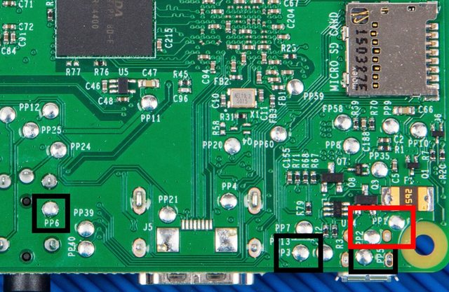
Although soldering directly to Pi's seems like a much more drastic measure to take I thought that it was worth the risk and that it was the solution that I ended up going with.
Next, I needed to tackle the cooling. Admittedly, this is where I went a bit overkill. I initially wanted to use the NF-A4x20 PWM fans by Noctua.
 Hardware Canucks
However, at almost $15 each, $30 for cooling 4 $30 computers just didn't really make a lot of sense. Then I came up with a different idea. As the length of the network switch afforded me extra room between the Pi's and the back of the cluster, the fans that I chose could be quite thick. This led me to pick 40mm server fans to use in the design.
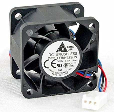
After they arrived I was disappointed to find out that the reviews of the fans being unbearably loud were true after some preliminary testing. However, they did push an unimaginable amount of air for their size so I decided to come up with a solution to tackle the noise.
My first idea was to hook up the PWM headers on the fans to the extra GPIO headers on one of the Raspberry Pi's and control it through temperature but that quickly became too far out of my element and probably out of the scope of the project. I decided to do the fan control the old-fashioned way by manually adjusting the voltage of the fans. To accomplish this I used a LM2596 Buck converter to limit the input voltage to the fans thus limiting the noise.
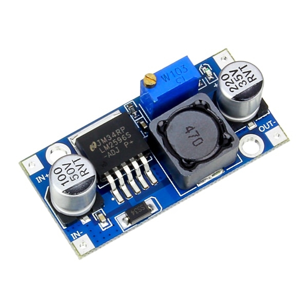
After some testing, I concluded that the optimum level for the fan speed was setting them to just 3 volts! Normally I would think that the fans wouldn't even be capable of spinning 9 volts under their rating but not only did they spin, when they were mounted into the enclosure I could feel a steady stream of airflow even through the USB ports.
Putting everything together
Now that all the systems have been explained it's finally time to show off what it looks like put together.
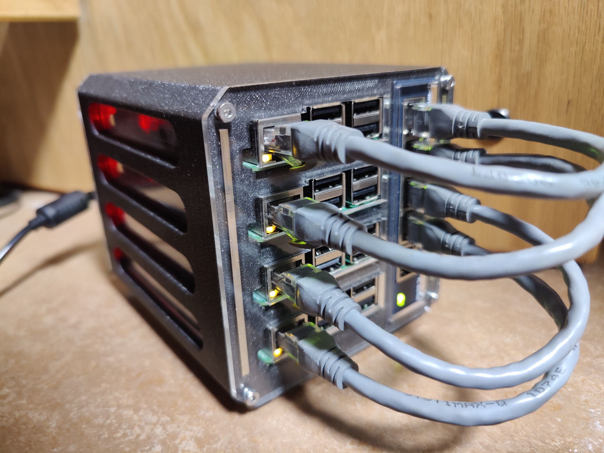
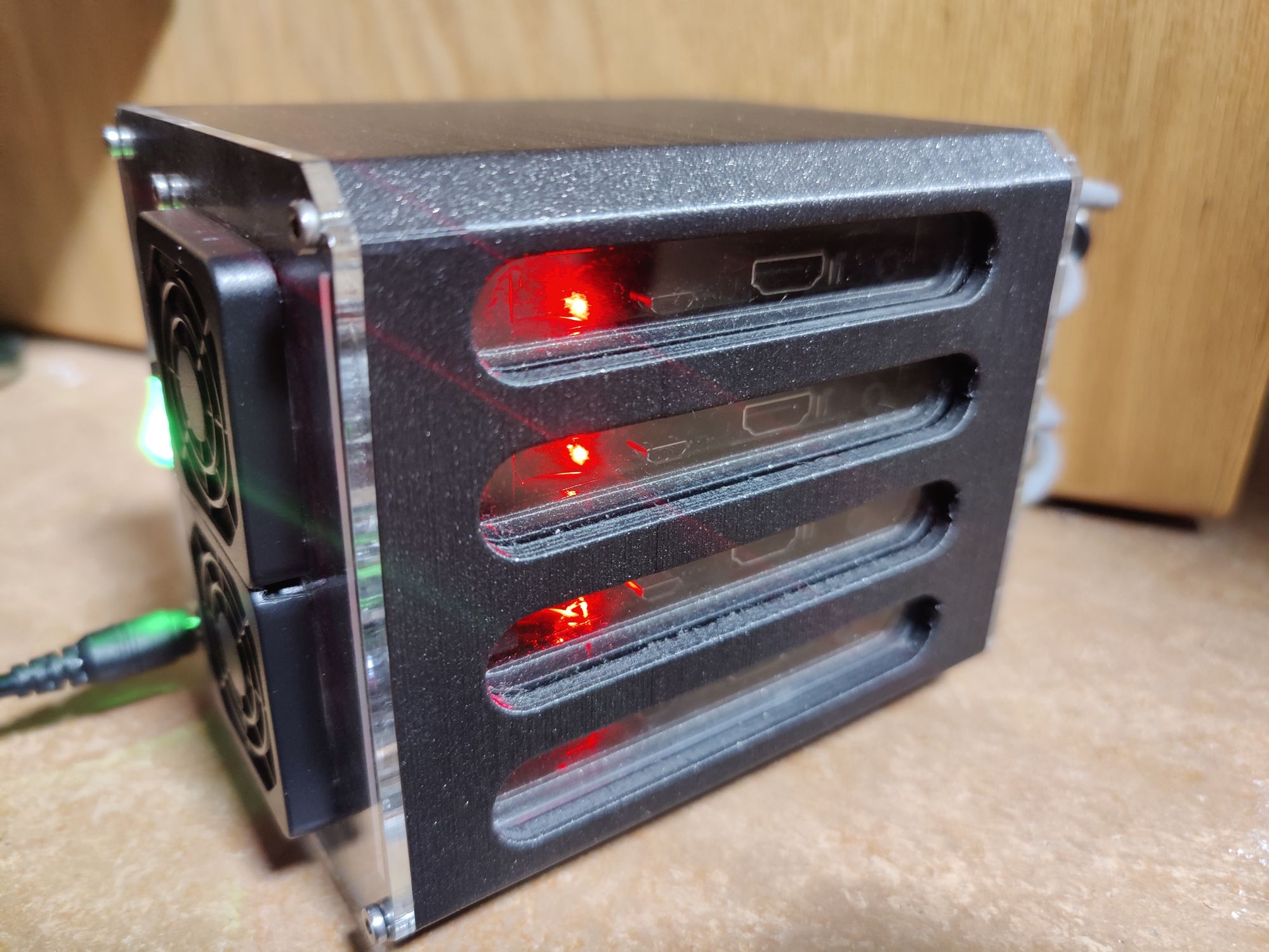
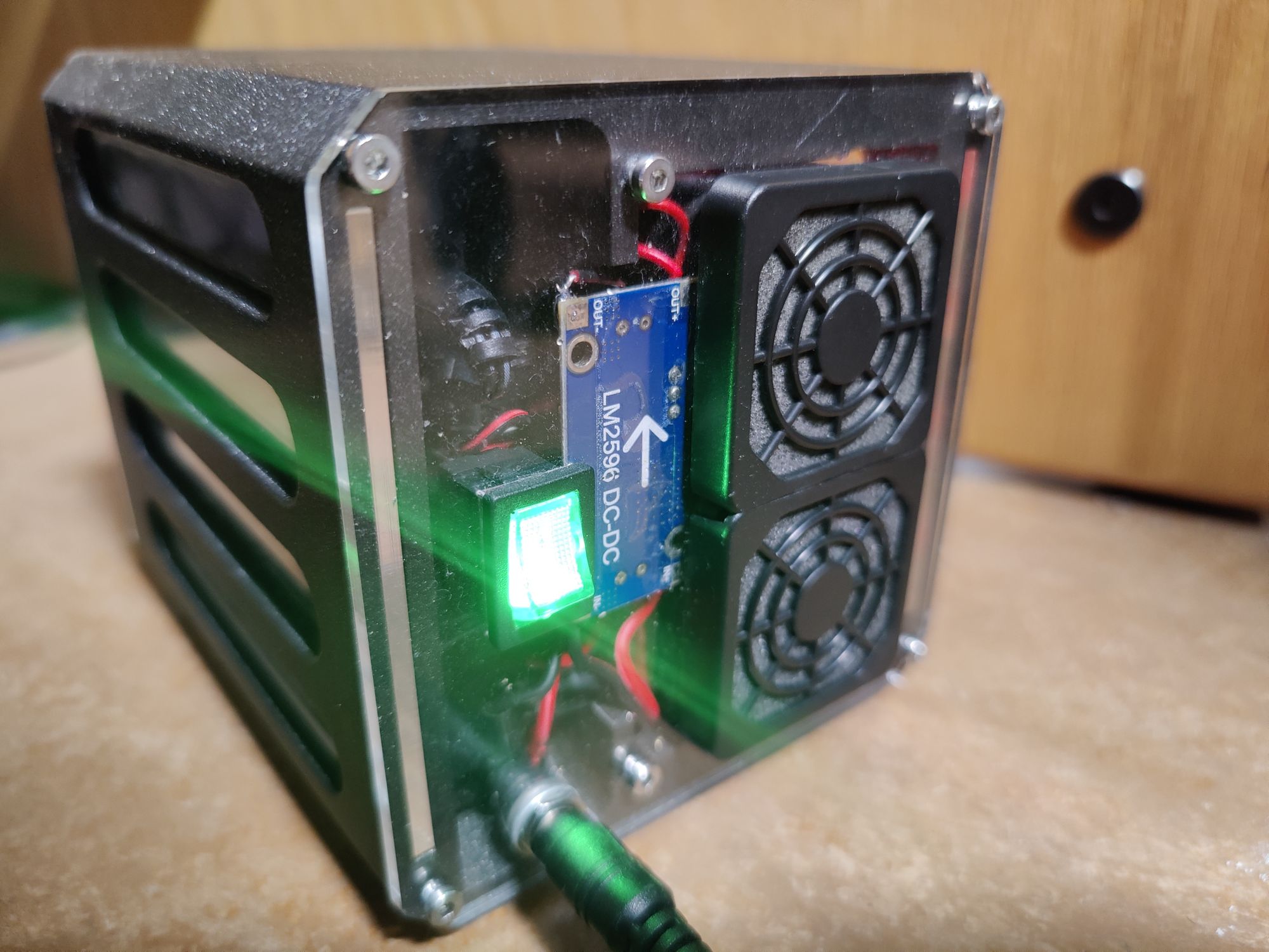
As seen in these photos there were some things added that I forgot to mention including the fan filters and power switch etc. Overall I think it came out really well and surprisingly accurate to my original CAD model.
So what do I actually use it for?
This is the main question that people are asked when you make these types of cluster projects is what people actually use them for. And to be perfectly honest there isn't really much you can do that you can't do on any normal server.
That being said, it was a really good learning experience and I am currently using my cluster to host a local PiHole adblocking instance and even the local version of this blog. All of the Raspberry Pi's are installed with Raspberry Pi OS running k3s, a stripped-down lightweight version of Kubernetes.
If you are interested in information to set up the software side of things, that is a bit outside the scope of what I can explain through the medium of this post, but linked below is an excellent video series by Jeff Geerling that I used as a basis to build my cluster off of.


This is a great guide for someone interested in setting up their own cluster from start to finish and I would highly recommend it.
Resources for building your own cluster
Here I am going to go over the basic steps and requirements for building your own cluster off of the design showcased above.
Requirements:
- x4 Raspberry Pi (2-3b+)
- x1 TpLink TL-SG105 Gigabit Network Switch
- x2 Sunon 40mm GM1204PQV1 fan
- x1 5v 5A Barrel jack power supply and female plug
- x1 Toggle Switch
- x1 LM2596 Buck Converter
- x4 6in Ethernet Cables
- x4 8gb+ MicroSD Cards
- x1 3-Way Screw Terminal
- x10 10mm M3 screws
- x8 25mm M3 screws
- x4 M3 Nuts
- Wire
- 3D printer
- Laser cutter if you want to be fancy
- Lots of patience
Below are the files that are needed to create this design. The assembly should be pretty self-explanatory just know that the 10mm M3 screws hold the panels to the 3D printed part while the 25mm ones and the nuts hold the fans. I have also included the files for the panels in DXF and STL formats if you do not have the means to laser cut them. The design should work just the same with them printed.
]]>