
Ironless Rotor Cycloidal Planetary Actuator

In my last SCARA arm project, I had a very frustrating experience designing high torque/high accuracy gearboxes for the Nema 23 stepper motors I used. Ideally for that project I could have used fancy off the shelf servos or QDD (quasi-direct-drive) actuators like the MIT Mini Cheetah. The problem with these is that they generally cost ~$500-1000 each, which is something I can't really justify for my projects.
This led me to want to develop my own QDD actuator with a heavy focus on keeping the cost low, both on the parts and tools needed to create one.
What's a QDD actuator?
A quasi-direct-drive actuator is a term referring to a type of actuator initially popularized by MIT with their Mini Cheetah actuator.
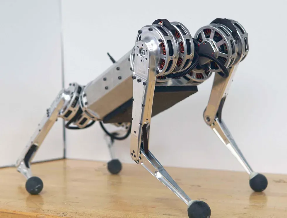
They generally consist of a radial BLDC motor with a gearbox reduction inside the stator that can heavily increase the torque while being extremely space efficient in their height. They are most famously used inside quadruped robots like the MIT Cheetah.
For this actuator, I don't have a final plan on what I am going to use it on just yet, but I wanted to create a platform that I could easily use and modify for my future projects.
Project Goals
The main goals I had for this project are as follows:
- Low cost, less than $80 per actuator
- Fully 3D printed, every single custom part is 3D printable. No machining, laser-cut metal parts, etc
- 10Nm of holding torque
- Easy to interface into my projects
Some of these goals present some challenges, namely needing to make the rotor and gearbox fully 3D printed.
Rotor Design
Every actuator design I have found online uses some sort of iron/steel backing behind the magnets in order to direct the flux of the magnets inside towards the stator. If my rotor is going to be made out of plastic, I wanted to try and make a design without a ferrous backing that doesn't give up significant performance.
To solve this, I chose to use a Halbach array like my previous axial flux motor project that was also fully 3D printed. This time I actually wanted to quantify the performance that I was leaving on the table by not using an iron backing.
I used FEMM to create magnetic simulations where I measured the static torque at a fixed angle for all three phase pairs of the motor. Then I created 4 different configurations to test how the different rotor designs affected performance: Halbach array with an iron backing, Halbach array with no iron, normal array with iron, and normal array without iron.
The results of these simulations are below.
| Rotor Config | AB Torque (Nm) | BC Torque (Nm) | AC Torque (Nm) | Average Torque (Nm) | % From Max |
|---|---|---|---|---|---|
| Halbach Iron | -0.915 | -0.310 | 1.824 | 1.017 | 100.000% |
| Halbach Ironless | -0.832 | -0.207 | 1.748 | 0.929 | 91.381% |
| No Halbach Iron | -0.953 | -0.293 | 1.540 | 0.928 | 91.328% |
| No Halbach Ironless | -0.791 | -0.243 | 1.175 | 0.737 | 72.455% |

These results were very interesting to me. Not only did the Halbach array have nearly identical performance to an iron-backed rotor, using both gets you a 9% bump in torque, which I would not have expected. This also goes to show how much performance I would be leaving on the table if I just used plastic parts without a Halbach array.
I also want to stress that I don't have a ton of experience in magnetism so if anyone has feedback on these simulations or tips for what I could change I would love feedback!
Using a Halbach array instead of an iron backing will also have much lower rotational inertia compared to an iron backing which is important for an actuator designed to quickly change directions.
Below is the final rotor design I came up with as a result of these simulations. As you can see, the magnet array is very dense with 42 12 x 5 x 3mm N52 magnets for the main pole pairs, and 42 1/2 x 1/8 x 1/16 N50 magnets for the Halbach pairs, both of which have a 0.7mm air gap to the stator.

Gearbox Design
The next big hurdle I had to overcome was designing a gearbox capable of handling the high expected torques of this actuator made out of 3D printed plastic parts. I chose to go with a planetary gearbox as it can usually be made more compact as compared to cycloidal or harmonic gearboxes.
The problem with 3D printing gear teeth is that most gear tooth profiles require sharp edges and because 3D printers extrude plastic out of a round nozzle, you are always going to have some sort of corner radius no matter how small. Plastic gears using traditional spur gear teeth also tend to run into shearing issues as the teeth are quite small and tend to fail at stress concentrations near the base of the tooth.

This made me rethink how I approached defining my tooth profile. The work I did on my previous cycloidal drive projects made me wonder if there existed planetary gearboxes that used cycloidal 'tooth' profiles.
Searching around I found out about pygeartrain, a Github project that can generate all sorts of crazy gearbox designs from mathematical functions. This can lead to some really wacky planetary designs such as this one. All credit for this goes to Eelco Hoogendoorn and he has a ton of other cool projects!

The problem is that pygeartrain was designed simply as a way to test and visualize gear profiles and not to create anything you could actually export to a 2D/3D model and implement into a design.
This led me to create a version that can create the cycloidal planetary gearbox profiles, allow you to give them actual dimensions, as well as create export files for actually modeling them out in SolidWorks. I also added functionality for creating helix and double helix versions of the cycloidal gear tooth profile.

Below is my Github repo where you can mess around creating your own wacky gear profiles with a full guide to turn those into 3D models.
For this project I chose to create a 7 to 1 gearbox visualized below.
As you can see with this gear profile, not only is there constant contact with no backlash due to the profile, you can also see the "teeth" are more like lobes in one continuous outline, which a 3D printer can easily create. Both of these benefits make these gears seem like they should be fantastic for 3D printed gearboxes, and I am honestly surprised I haven't seen anyone try this before.
Creating the integrated design into my actuator from these exports was slightly more complicated. Below is the final gearbox module that goes through the center of the actuator.


Stator and Windings
For the stator, I chose to use a 10010 stator as they are cheaply available online and fell roughly within the size I wanted the stator to be. This is a 36 slot stator so I chose to use this winding configuration that I got from the bavaria direct winding calculator. For the windings, I chose to do 6 turns (5 full, 1 partial) around each slot, winding 6 strands of 0.4mm diameter wire in parallel.

Here is a render showing how the stator is assembled into the clam-shell of the gearbox module.

The Final Actuator Design
Now that I had designed a rotor, gearbox, and chosen what stator I wanted to use, it was time to put everything together into one cohesive design. I wanted this actuator to have an integrated controller and to keep costs down I chose to go with the MKS X Drive Mini. This is a low cost controller based on the older ODrive 3.6 and has a built in hall effect encoder making it suitable for integrating directly into the actuator.
I would have liked to use a proper new ODrive or a moteus controller, but they are hard to justify as they cost 2-5x more than my entire actuator design for just the controller.
Here are some renders of the final actuator design that I came up with.


Here is a cross section of the actuator with all the 3D printed components colored.

And here are the final bounding dimensions of the actuator.

Fabrication and Assembly
With all the custom parts on the actuator being 3D printed, most of the motor fabrication was just printing the components out. I printed all of the parts out of PA6-GF for some extra strength but I probably should have used just normal nylon filament for the gears if I had to do this again because the glass additive might cause abrasion over time.
I did go through quite a few prototype parts making this though as I went through several different designs for nearly every part.

When assembling the rotor, I created a fixture to hold all my magnets at the desired air gap and then slid them in from the bottom. There are radial holes behind every magnet that I used to superglue them in place from behind after all the magnets were slid in place.


Finished rotor (left), Magnet insertion fixture (right)
For the winding, it was a bit more complicated. I started by using the incredibly advanced tooling seen below to split 1 large spool into 6 smaller ones and then I fed all 6 through an equally sophisticated enclosure to get ready for winding.


Photos for how I set up each individual copper spool and fed them all together to wind the stator
I then completed the arduous task of winding each phase, which in total took about 3 hours. After that, I took the wound stator to an LCR meter at my university in order to check the phase resistances and see if I had made any winding mistakes.


Finished wound stator as well as testing on the LCR meter
The results from the LCR meter are below. As you can see the tolerance between coils is incredibly good and far better than any of my other motors.
| Resistance (mΩ) | Impedance (μH) | |
|---|---|---|
| ɸA | 62.36 | 33.92 |
| ɸB | 62.42 | 33.04 |
| ɸC | 63.31 | 33.92 |
| Tolerance | ±0.76% | ±1.31% |
After assembling the gearbox with some lithium grease for lubrication I completed the assembly of the actuator.
Here is a video where you can see the gearbox working.


Final assembly (left), gearbox (right)
The final actuator has zero backlash, has little to no resistance when back-driven, and weighs in at 728 grams.
Testing
To start off testing this actuator I printed a 250mm arm that I could swing around and use to have a nice visual when calibrating the PID values for the FOC controller.
Here is a video of one of the first times I actually got it moving.
I also needed to figure out the torque constant and Kv for further tuning of the actuator. To do this, I backdrove the actuator with a power drill at a known RPM and measured the voltage generated from one of the phases.

From this, I calculated that my actuator has a Kv of ~79, which lines up with what I would expect and allowed me to calculate the torque constant for the ODrive config.
After I got it nicely tuned, I set up my lab scale below the end of the arm and did a simple test to see what the holding torque would look like.
In this test the motor was able to hit a peak holding torque of 14Nm which was decently above my goal of 10. However, even with it outperforming it still looked like there was room to go further. The actuator only stopped because it had reached the current limit of my 24V 25A Meanwell power supply.
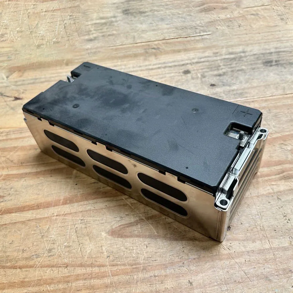
That meant I needed to find a DC power source that could push a lot of current. After asking around some forums for a power source people recommended for a project like this, I was pointed in the direction of reclaimed battery modules out of EVs. Luckily for me, after seeing my messages, Peter Holderith (@_baldtires) said that he had an extra module from an Audi E-tron that he didn't need and would send me for free.
This was extremely helpful and was the only way I would have been able to complete this project, so a big thanks to him. Check out his cool projects at the link above.
The module is able to be charged to 50V and has a maximum peak current output of 400A. 20kW of power was more than enough for what I would need during my next test, so I created a new setup powering the actuator off the Audi module.
For for this next, test the actuator had well exceeded the limits of my lab scale, so I hooked a string to a force gauge and pulled the actuator perpendicularly to the arm.

I also set up thermocouples inside the coils in order to see when I would be getting close to melting the insulation.
With this setup I was able to reach a maximum holding force of 117.5N which equates to a holding torque of 29.4Nm with the wires reaching a surface temperature of 78°C. Even in this test there was no mechanical or electrical failure and it only stopped because the controller had reached the 50A current limit I had set. However, I got the feeling that I was reaching the edge of what both the coils and plastic gearbox were capable of, so I left it at that. This gives the actuator a respectable torque to weight ratio of 40.38Nm/kg.
One crazy thing is that after a test of the actuator holding ~30Nm of torque for several minutes, there was still no perceptible backlash in the gearbox.
Cost Breakdown and Building Your Own
Of all the stuff I have created on this website I think this project is definitely something that people could benefit from and use in their own projects. This was the driving reason why I wanted to make this as low-cost as possible. The final bill of materials breakdown is below.

As you can see the final cost per actuator is just around $40 for the actuator and 70 if you include the controller.
This gives the actuator a cost to torque ratio of $2.47/Nm.
This is one of, if not the cheapest, actuator I have found online that has this level of performance.
All the motor CAD, FEMM simulations, BOM, and the ODrive config are open source and found via the link below. I only ask that If you use these files for your project that I be credited.

Conclusion
Out of all my projects this one was by far the one I had the most fun making. A lot of my other projects have mostly been useful for me to learn different things, but there wasn't much application in the final product. For this one however, I think I was able to implement some very novel ideas into a cost-effective end product that solves a real problem that I and hopefully others have. This project very much feels like the culmination of all my other motor projects, and I am really excited to see how people build off it!
Caden Kraft Newsletter
Join the newsletter to receive the latest updates in your inbox.


