Solar Car Steering Wheel
At Iowa State University, one of my main interests has quickly become the PRISUM Solar Car Club. It has given me an opportunity to use my engineering skills outside of classes with some pretty cool people.
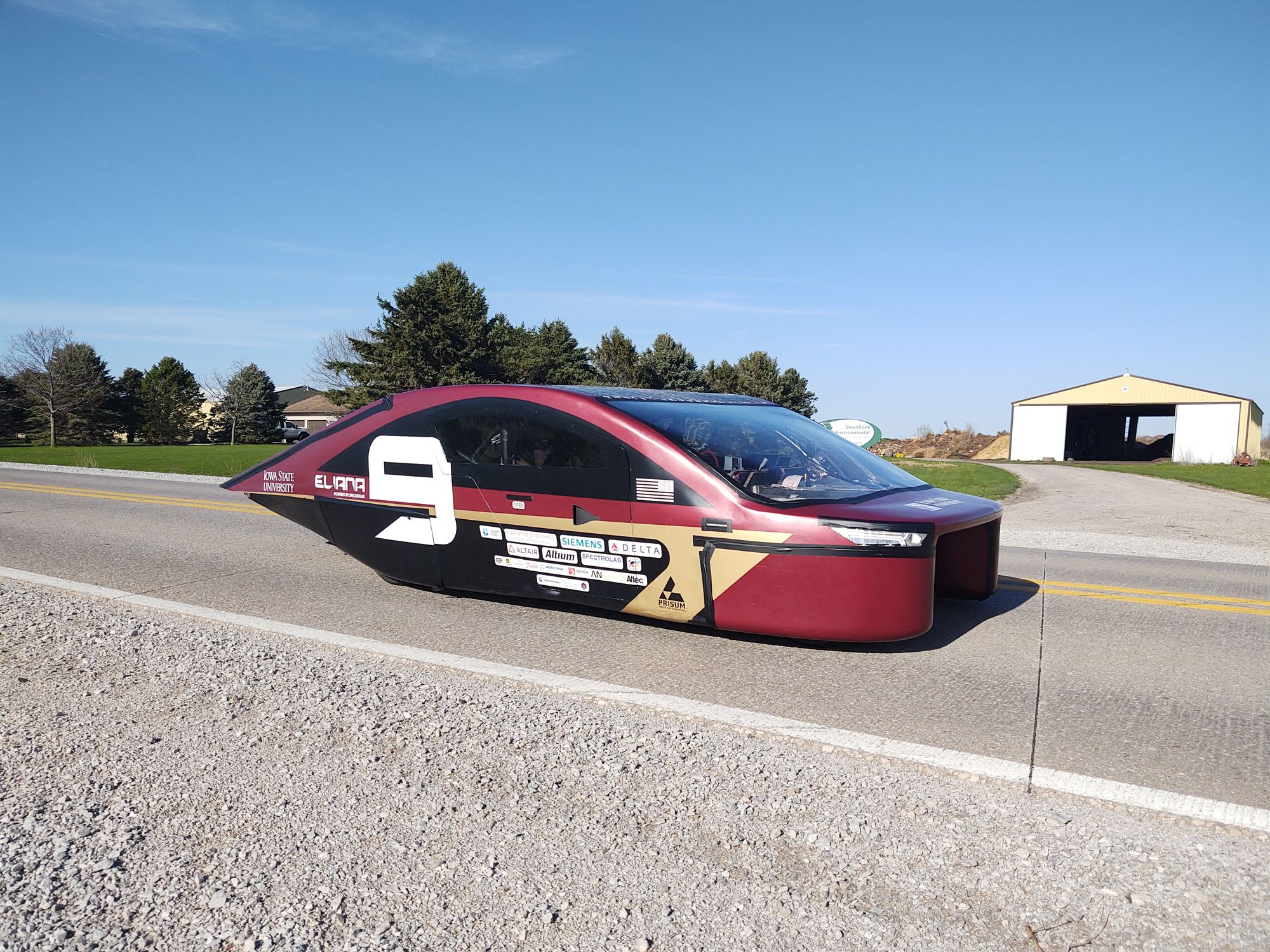
As I am a Freshman at Iowa State, and at the time of writing P15 is coming to the end of its build cycle, most of the core systems in the car have already been set in stone. However there are a few smaller projects that haven't been tackled yet.
One of these projects is redesigning the steering wheel. The current steering wheel in the car has given us many problems that have greatly inhibited our ability to drive reliability without breaking down. Looking at the image of the disassembled current steering wheel below you can see that it mostly consists of a waterjet sheet of carbon fiber with holes drilled for the quick disconnect fitting and the buttons used for turn signals, hazards, etc.
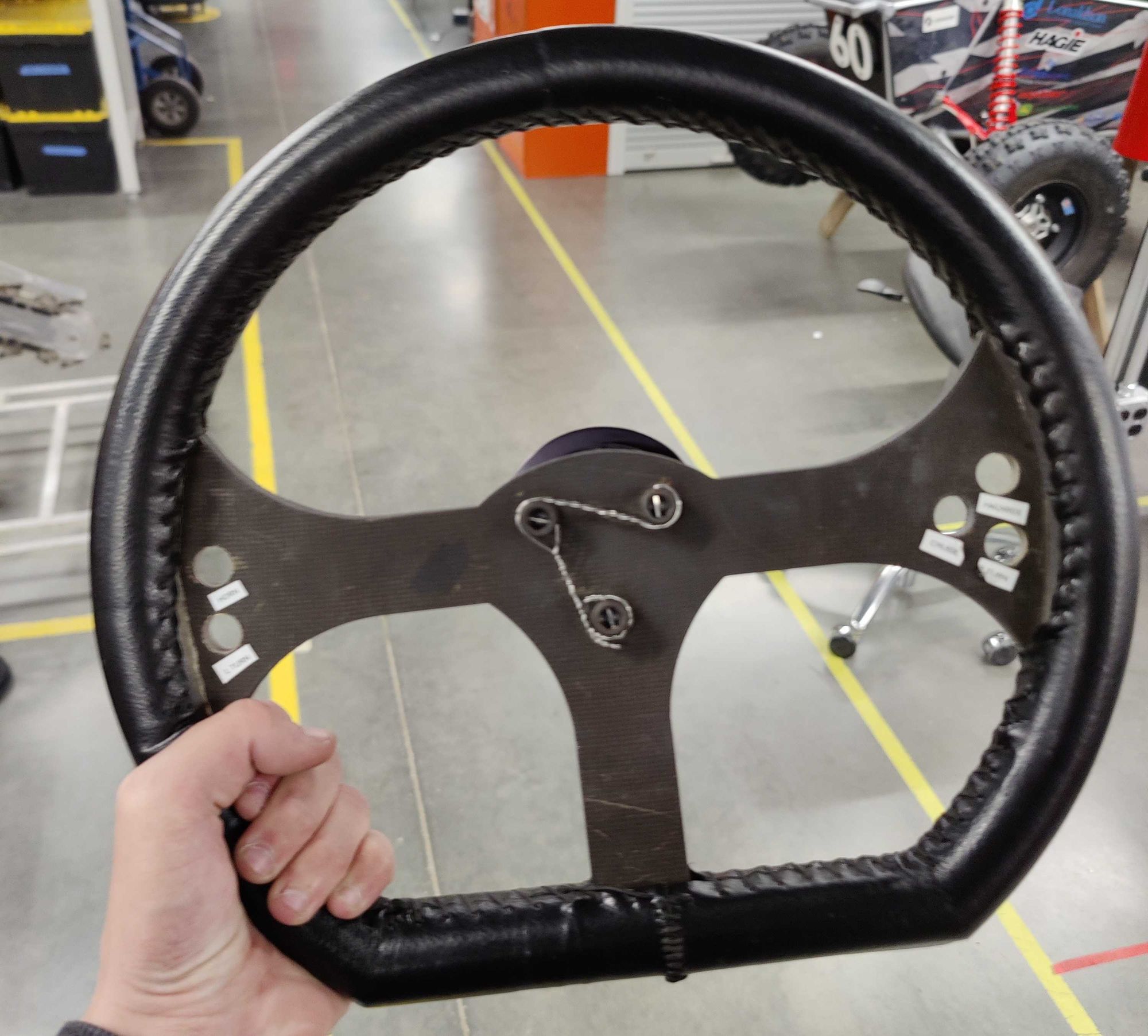
The problem with this design is that the wires that connect to the buttons to the aptly named buttonboard PCB that controls them, get individually routed to buttonboard deeper into the car. This means that when rotating the steering wheel, as there are more than 15 individual wires being rotated, over time some either develop a loose connection or snap off entirely.
As the steering wheel controls everything from turn signals to our regenerative braking we cannot have these faults inhibit us from driving at race this summer.
Some other smaller issues with this design are that as the holes for the buttons are drilled, the number of them and their positions are fixed and can only be redone by re-waterjetting the main carbon panel which can cost up to $50 in materials and machine time. The hole pattern was also drilled by hand with no CAD available which makes creating a strain relief component that integrates with the current design quite challenging.
Taking all this in mind I started on defining the requirements I was going to set for myself for the new design to meet.
- Integrate the buttonboard PCB into the steering wheel itself
- Limit the connection from the steering wheel to the car to a single wire
- Provide the ability for the button position and count to be quickly redesigned if needed
- Utilize 3D printed parts as much as possible and mechanical fasteners over adhesives
With these in mind I started to design the steering wheel. I jumped into Inventor and started modeling and after a few hours was left with my first iteration.
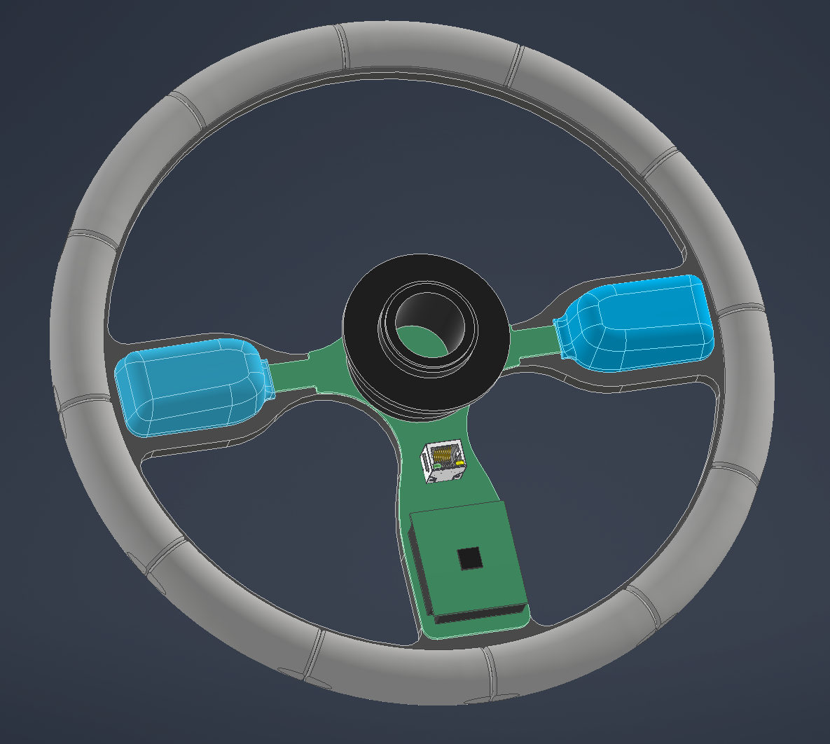
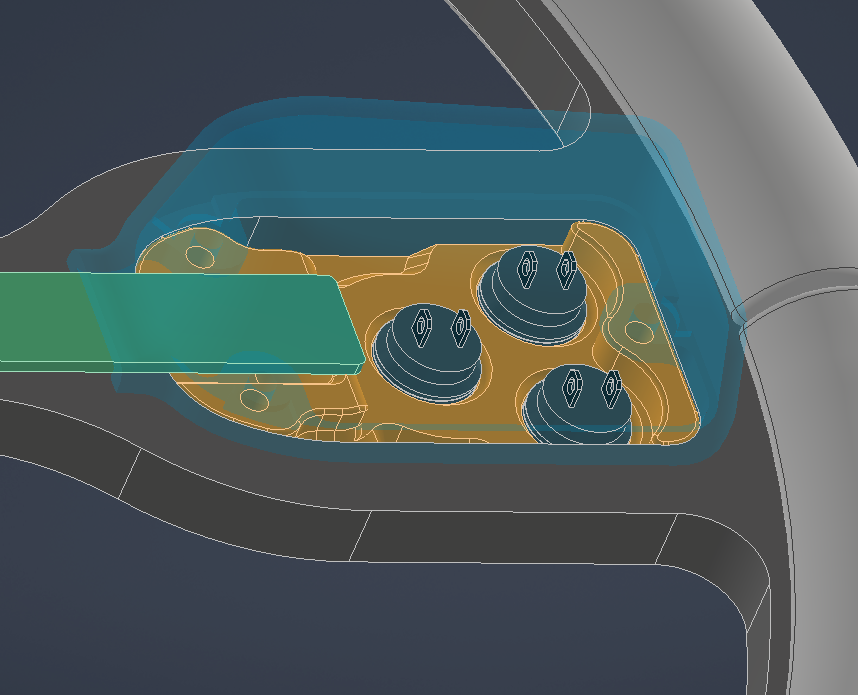
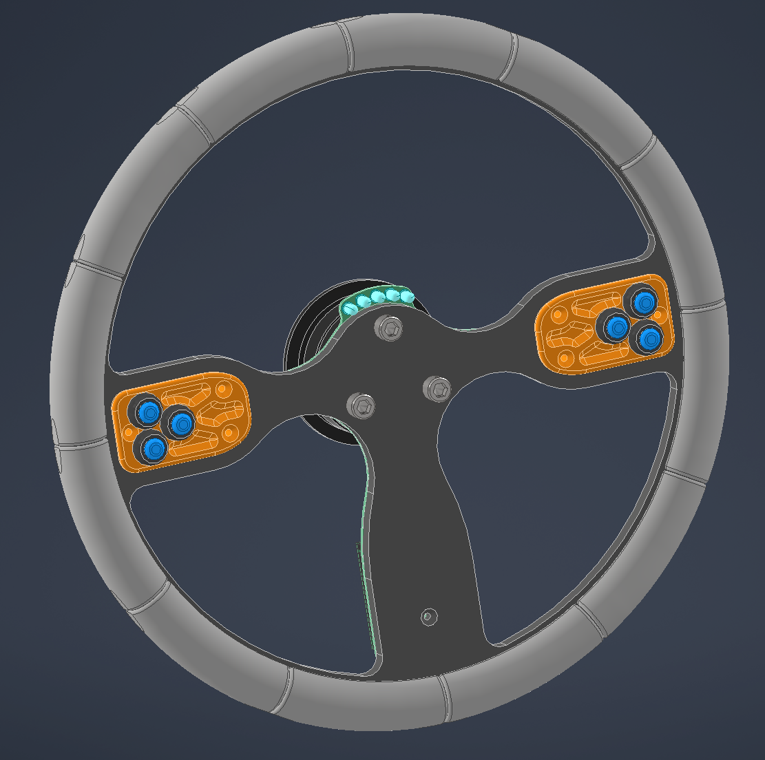
Various views of the first iteration steering wheel design
As seen above, there are many aspects to the new design including the integration of the buttonboard PCB shown as a placeholder in green, with the smaller PCB being the compute module needed to run the code. There are also 3D printed redesignable inserts for the buttons combined with an RJ45 Ethernet jack used in order to transmit power and CAN data from buttonboard to the rest of the car.
I showed this design to the team and received a lot of really helpful feedback. The core areas of feedback are as follows.
- This design is larger than the current one and takes up more space in the solar car. Some drivers noted that the current one already got in the way often
- Much of the PCB and compute module are unprotected which could lead to damage from it being handled so much
- PCB shape and size could lead to increased manufacturing cost from the PCB fabricator
- Add some sort of gasket between the PCB and carbon panel
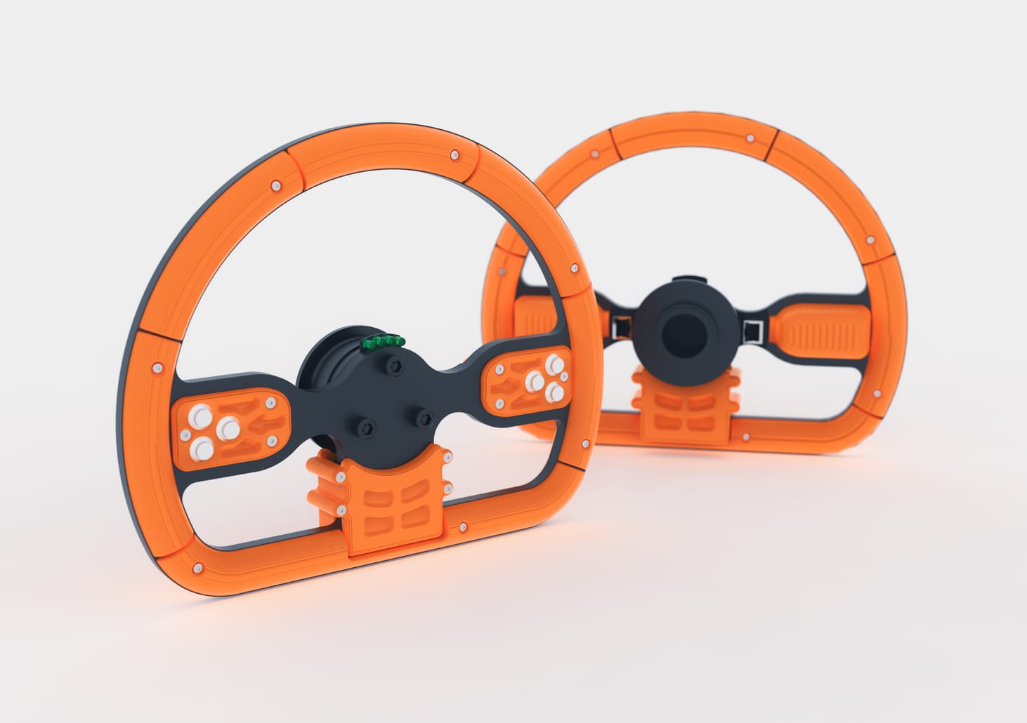
With this feedback I embarked on creating a second more compact and integrated design that could also fufill the new requirements of smaller size as well as protecting and optimizing the shape of the PCB.
I culminated this all into a brand new design to which a draggable view of it is seen below.
This new design includes numerous improvements from the first namely being, compact size and increased protection around the PCB and exposed electronics. It also has 2 RJ45 connectors in case one fails.
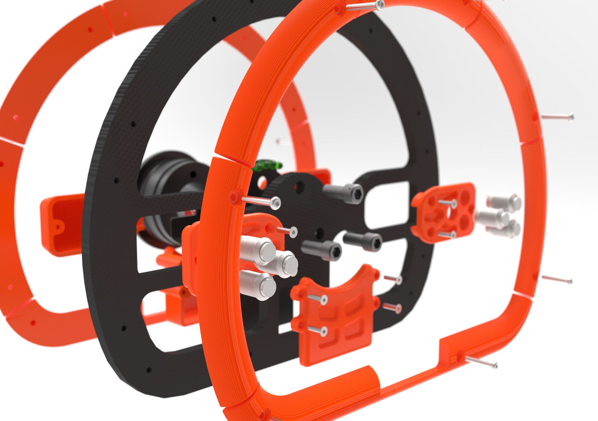
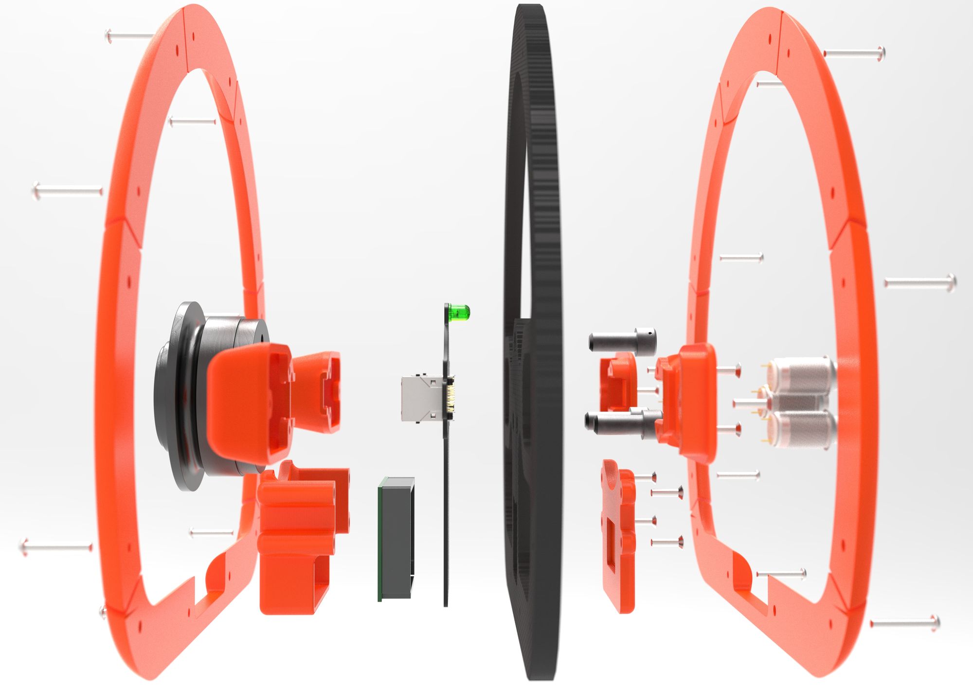
Seen below are areas on the new design with increased protection around the electronics.
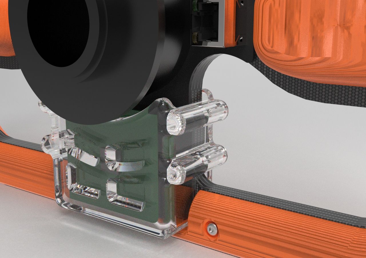
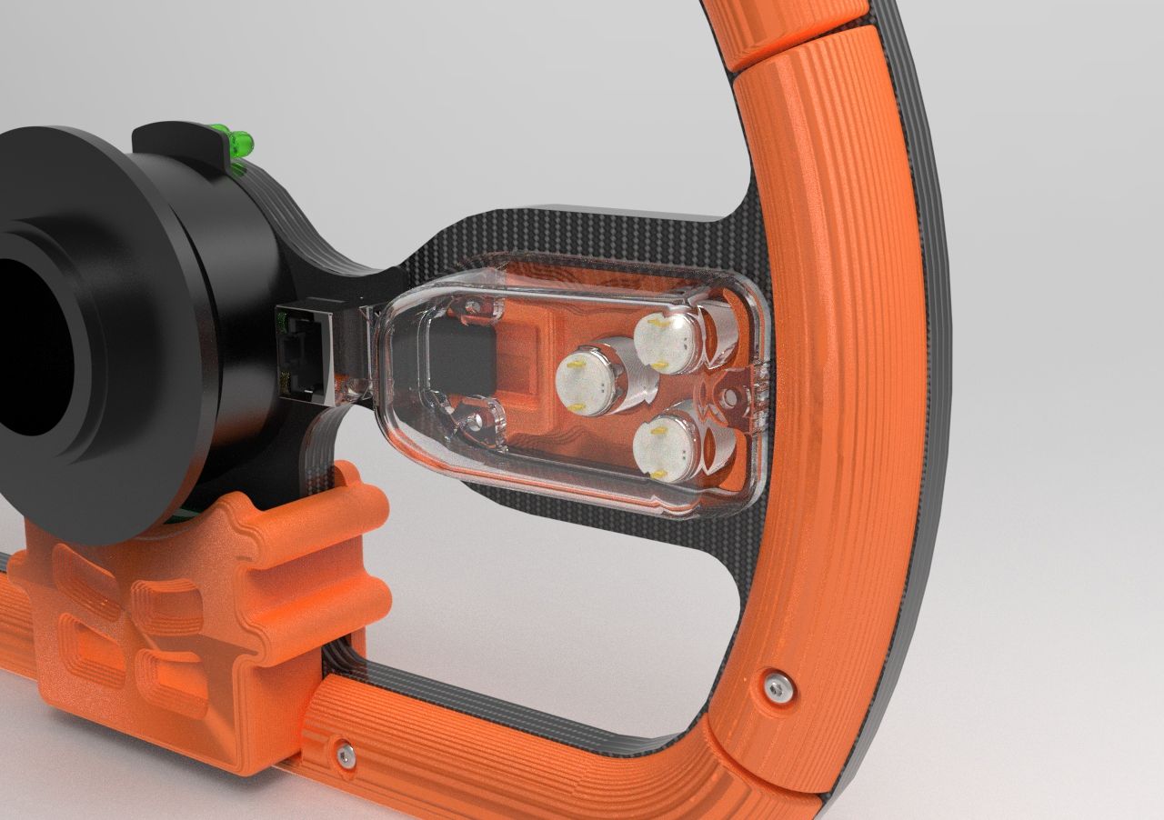
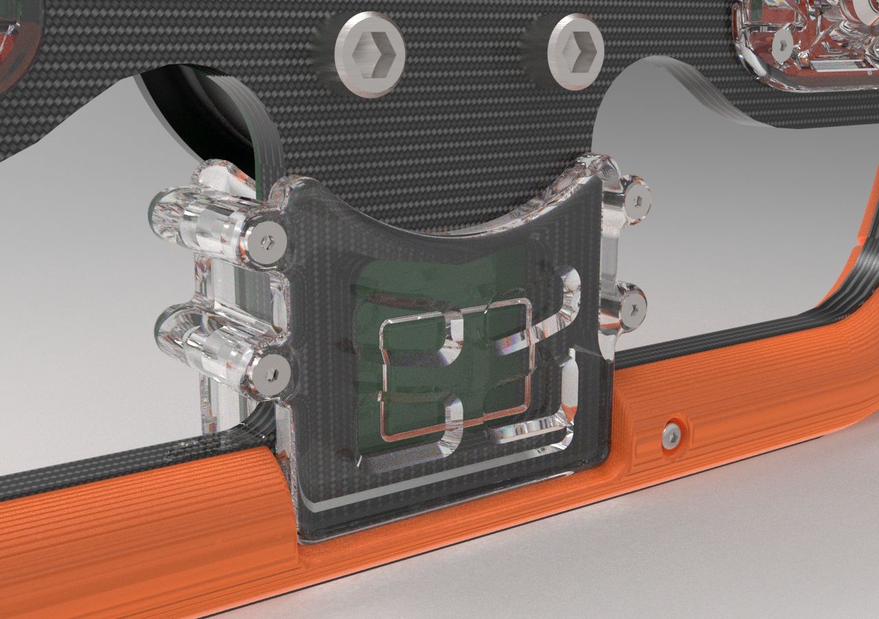
Compute Module Cover (left), Button/Wire Cover (center), Front Component Cover(right)
After showing this design to the team nobody had issues to raise on the second iteration so I began working with the electronics team to develop the new buttonboard PCB meeting the form factor of my new design.
I started off by exporting the outline of the PCB placeholder I created in Inventor and opened it up into Adobe Illustrator where I marked areas where electronic components could not be placed as the PCB would be directly against another part.
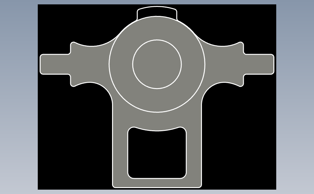
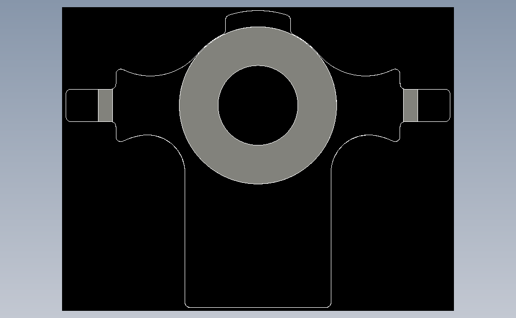
Outlines of PCB part placement
These outlines could then be imported into Altium Designer, our teams' PCB designer. Members of the electrical team were then able to convert this into a PCB board outline and start the process of creating a board schematic and placing components.
Here is the finished design that they came up with below.
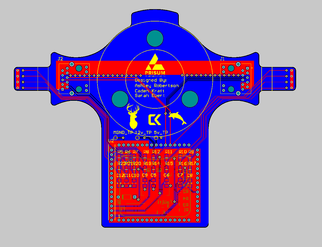
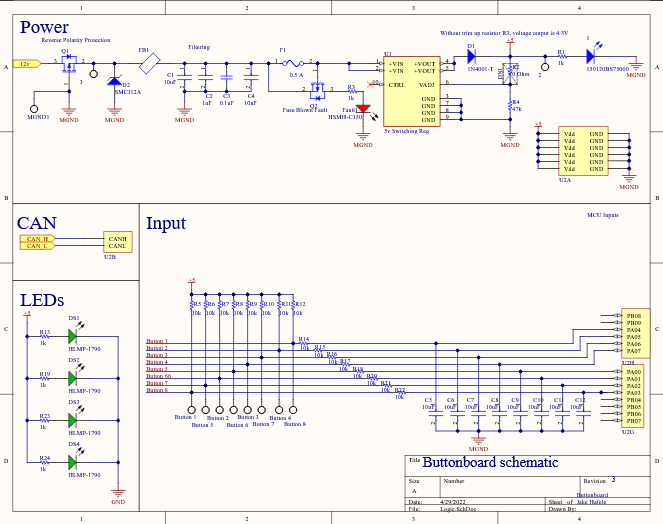
buttonboard PCB layout (left), buttonboard schematic (right)
With this step complete we were able to order the PCB and its components and I was able to start manufacturing the mechanical parts needed for assembly.
While the center peice was again waterjet out of the same carbon material of the first, most of the components were 3D printed using the 3D Printing Club's print lab in Prusa3D PETG plastic to provide temperature resistance during the hot summer temperatures they will endure.
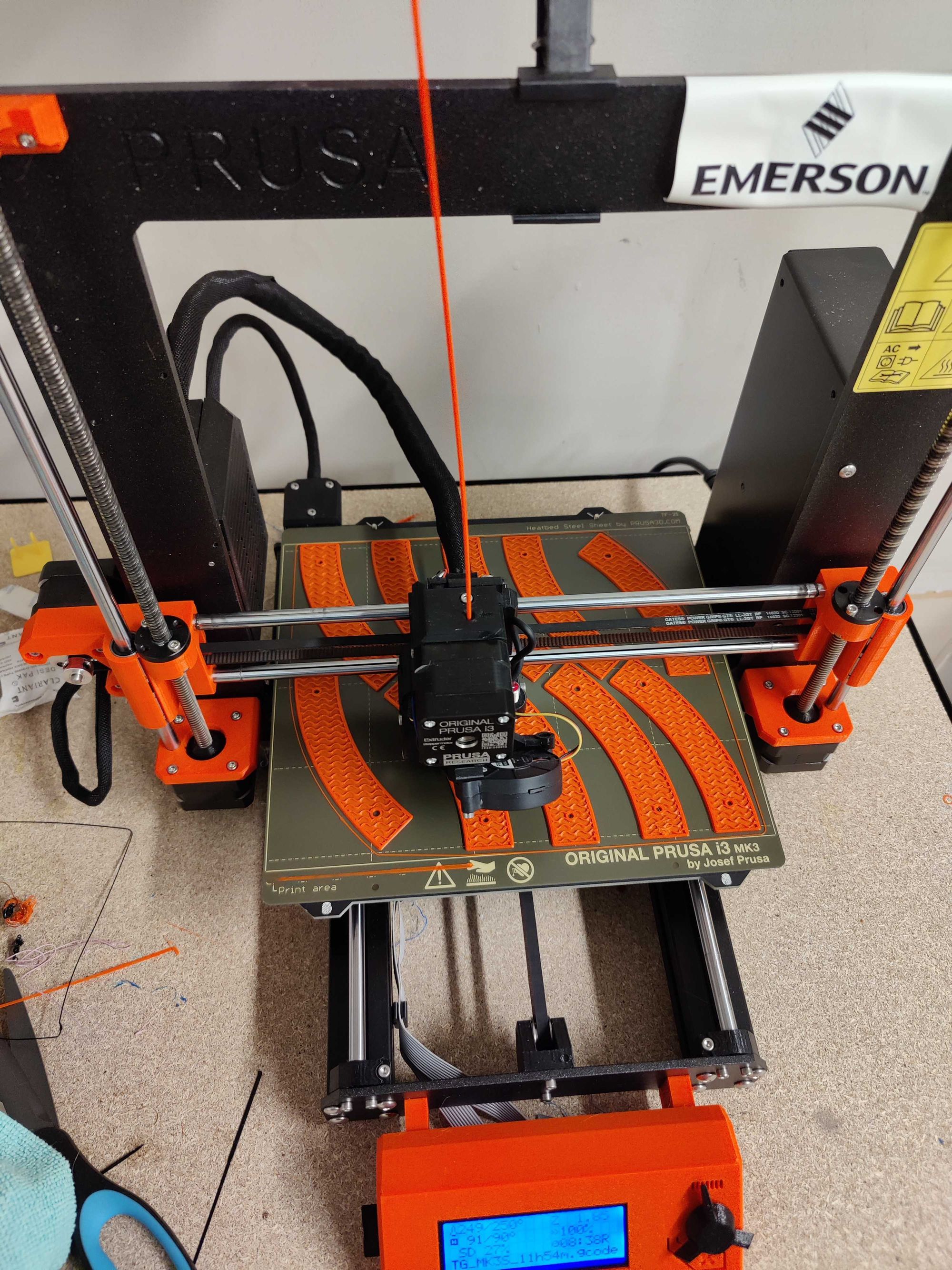
Once all the parts were printed and the carbon plate was waterjet I soldered and tested the components onto the brand new buttonboard PCB.
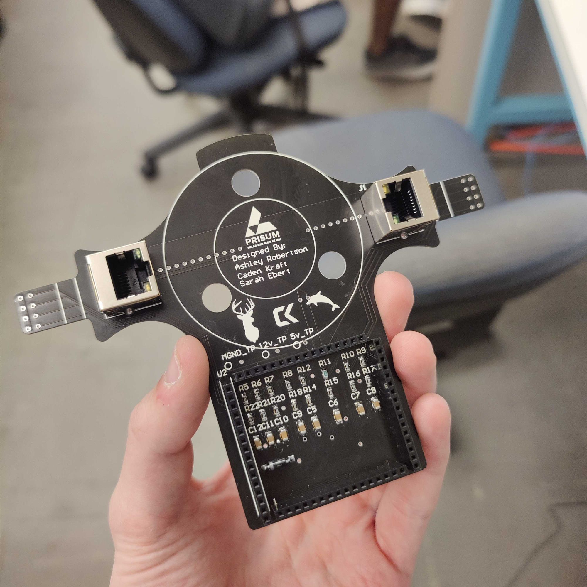
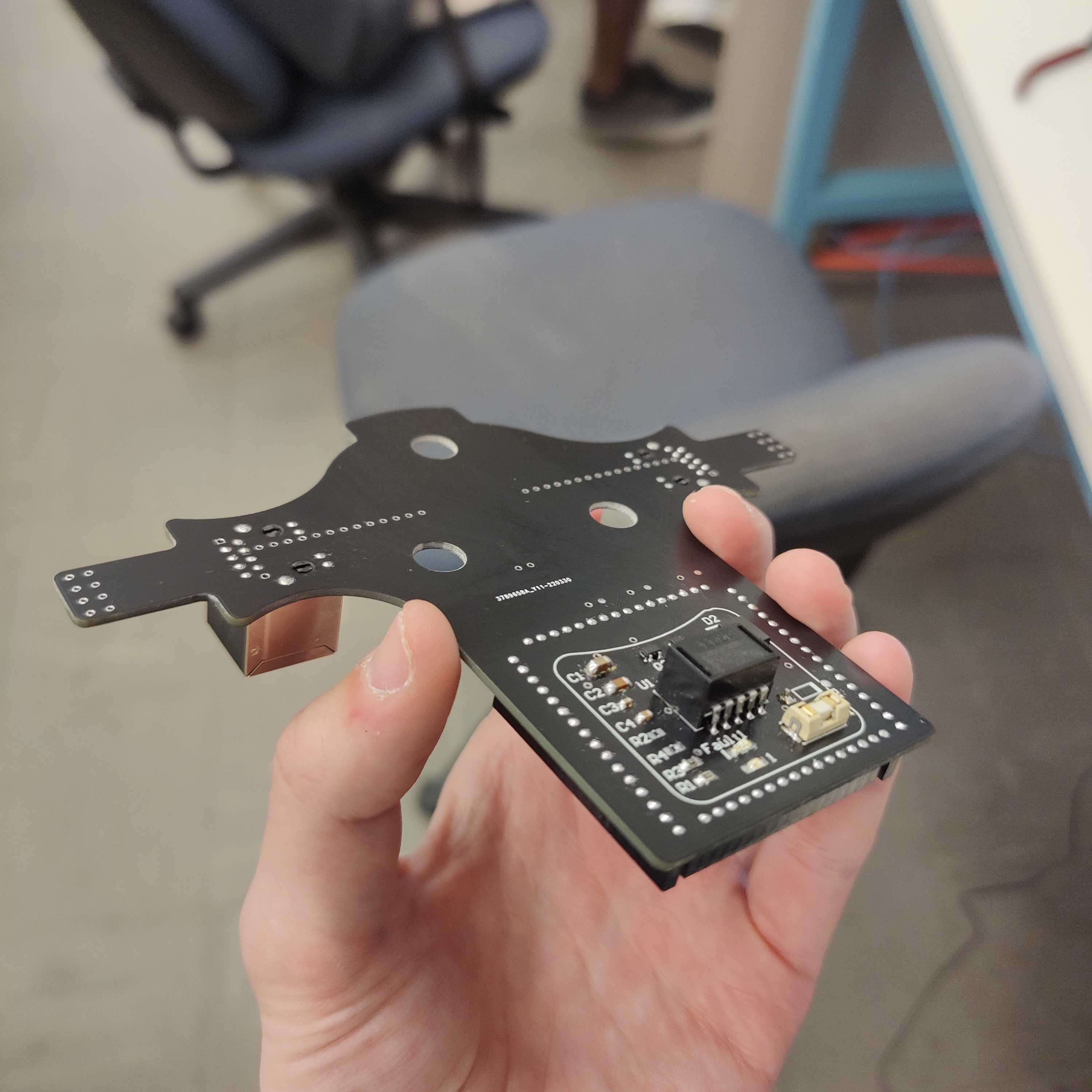
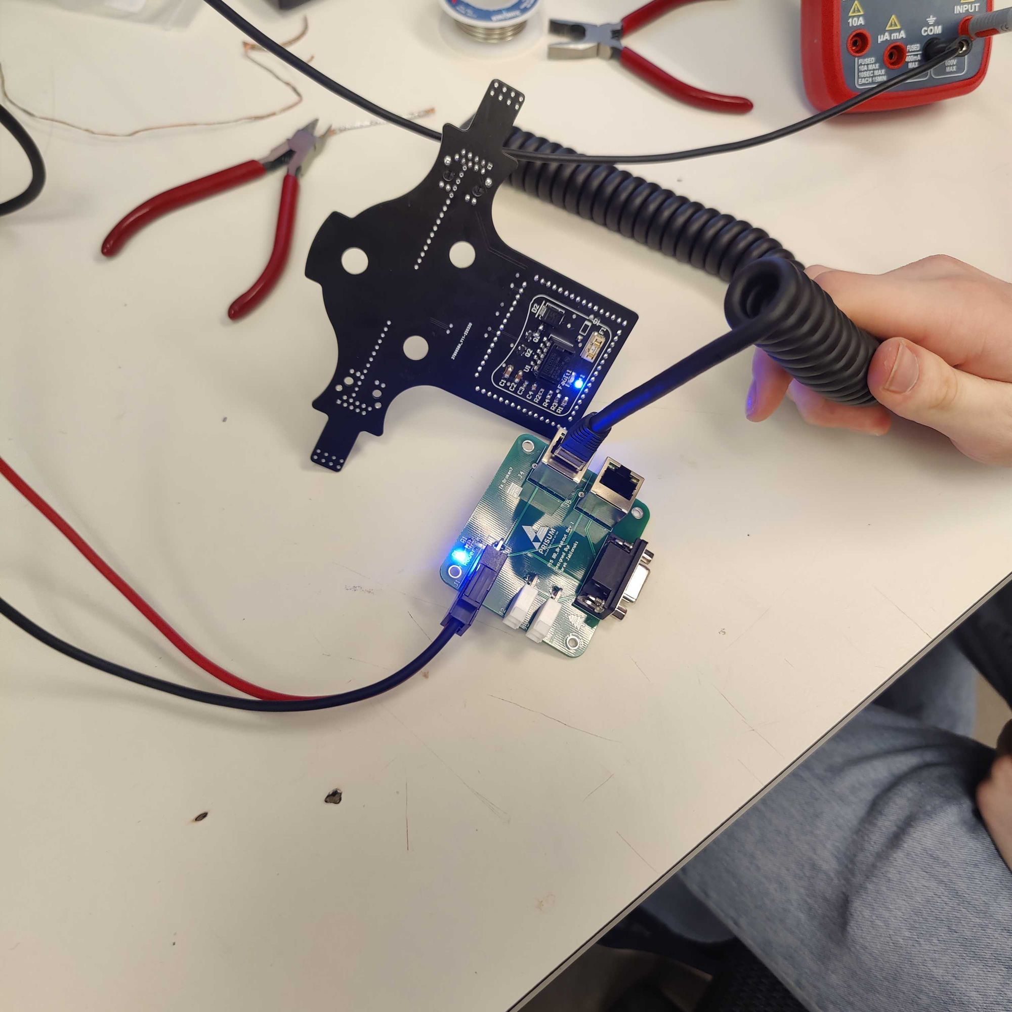
Soldered buttonboard PCB (left, center), Buttonboard testing (right)
Finally, all the parts were ready to assemble. Here are some images documenting the assembly of the finished product.
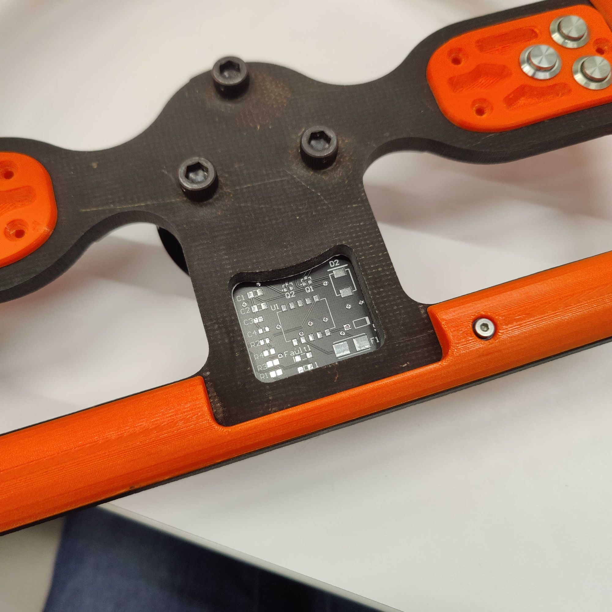
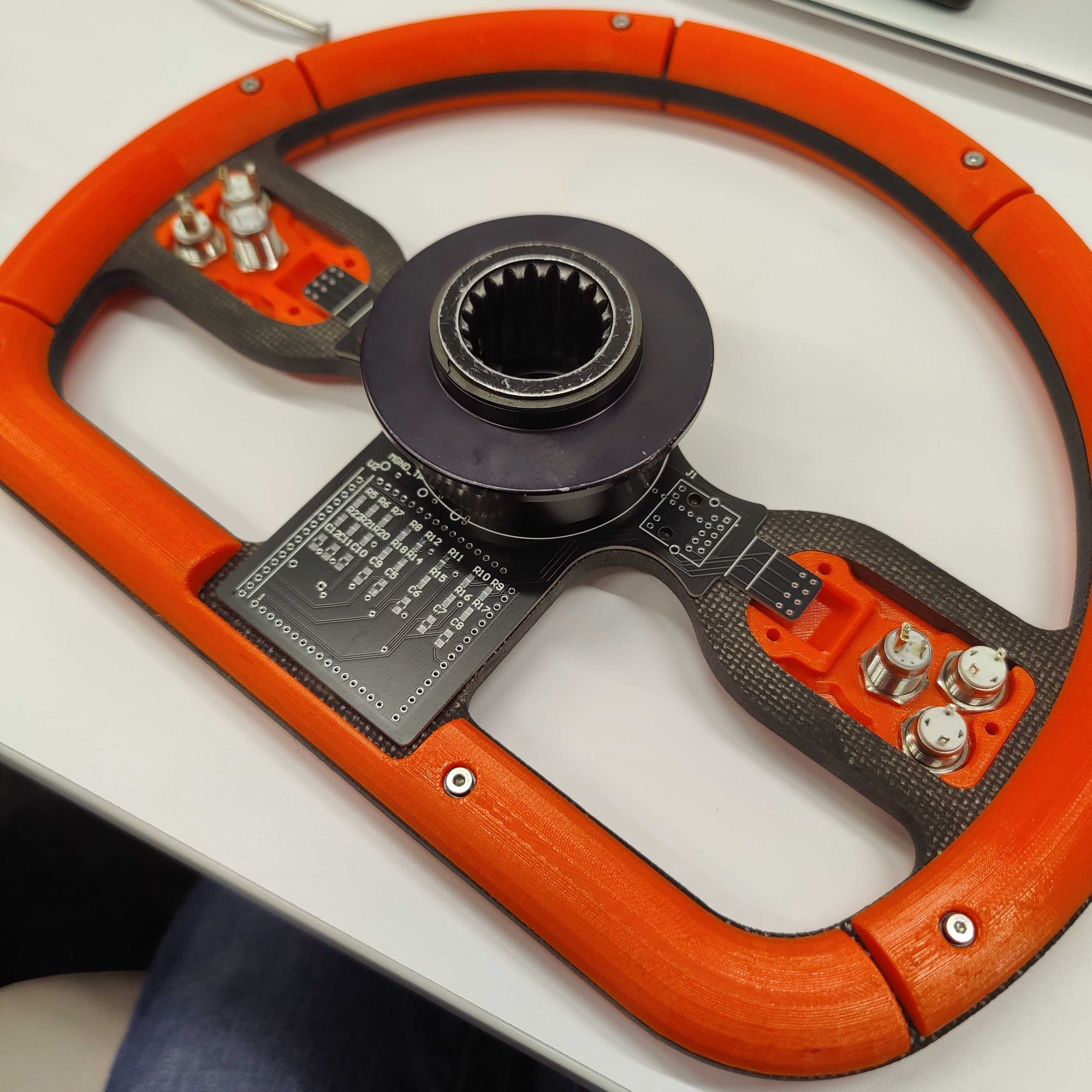
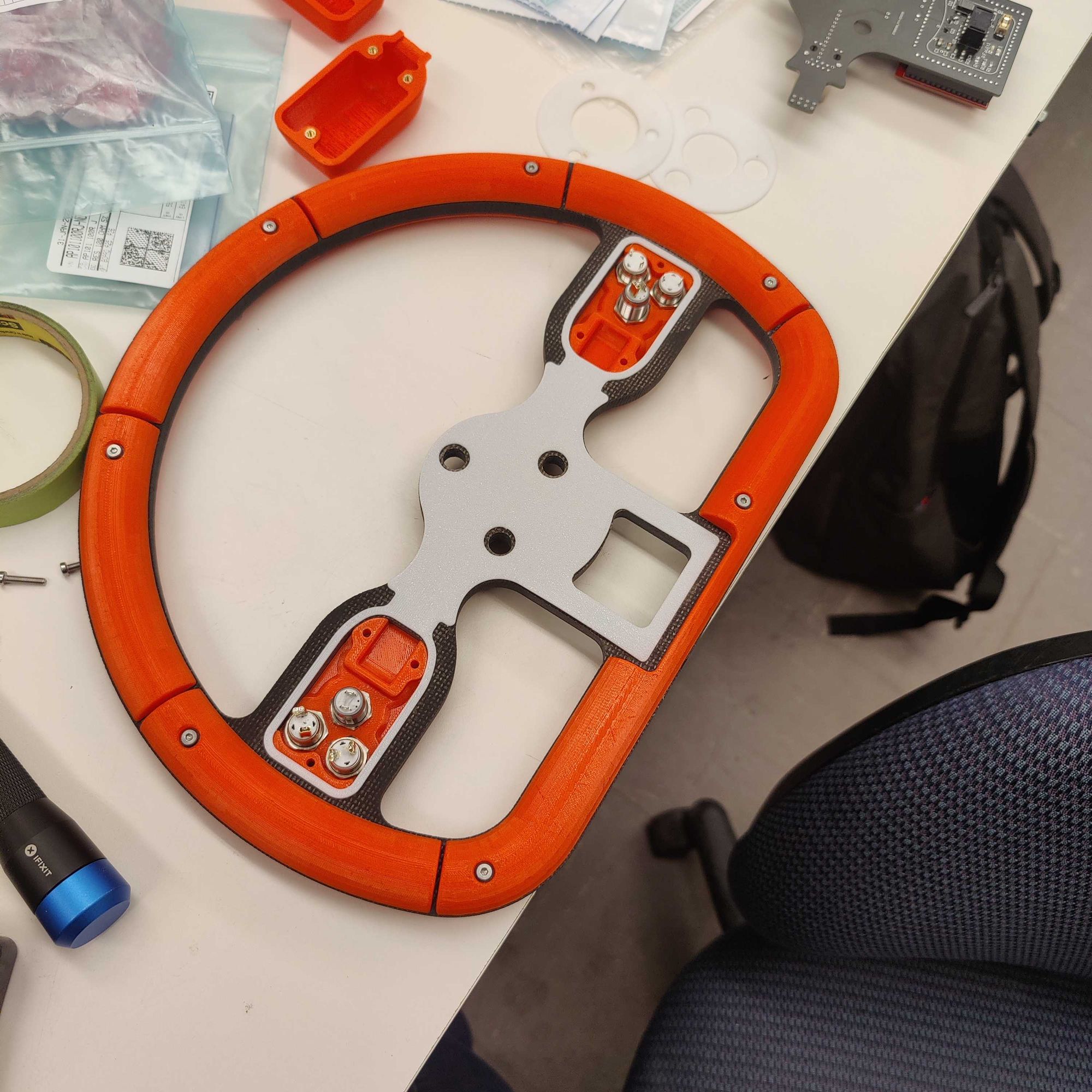
Front PCB area (left), Wheel assembled without back covers (center), 3D printed rubber protection gasket (right)
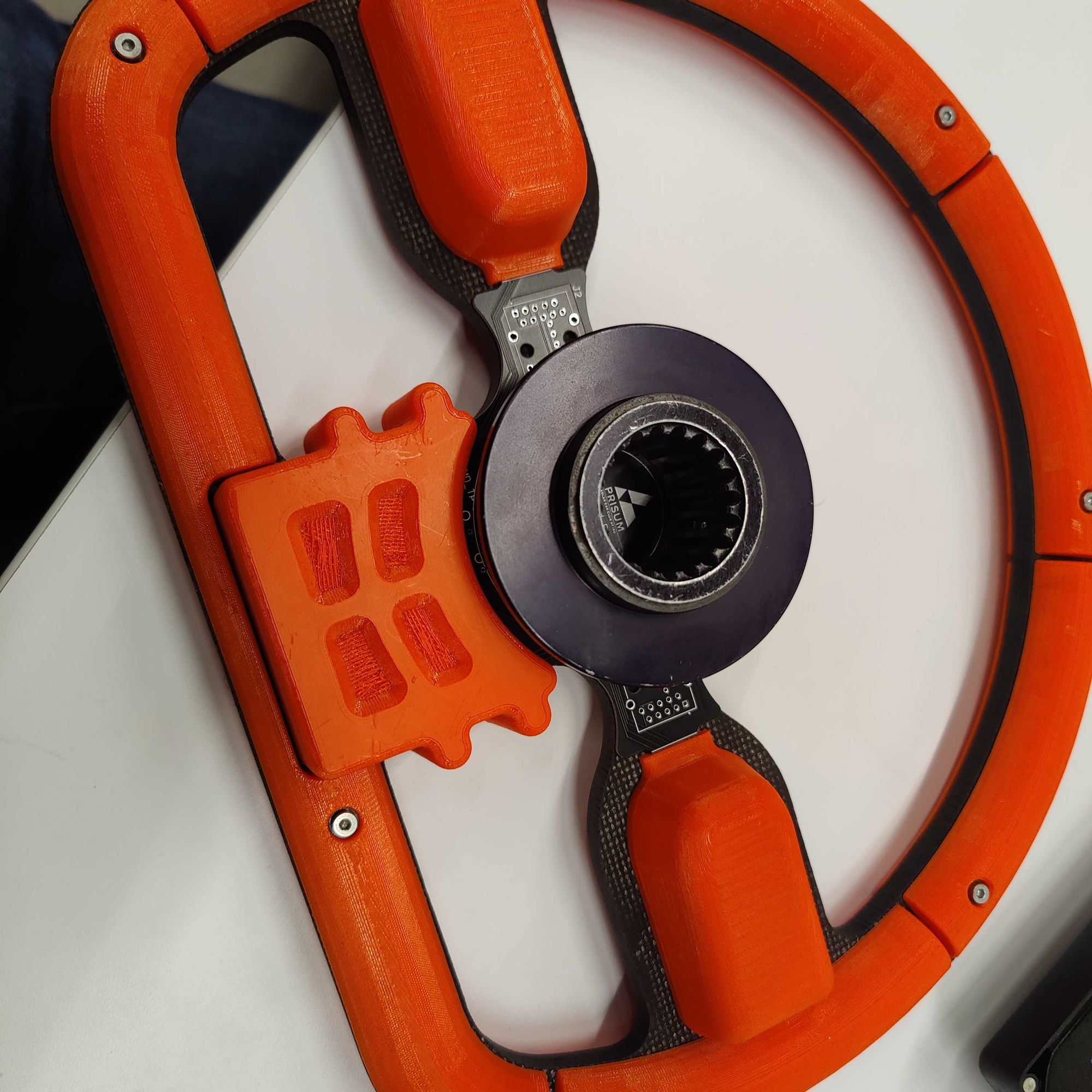
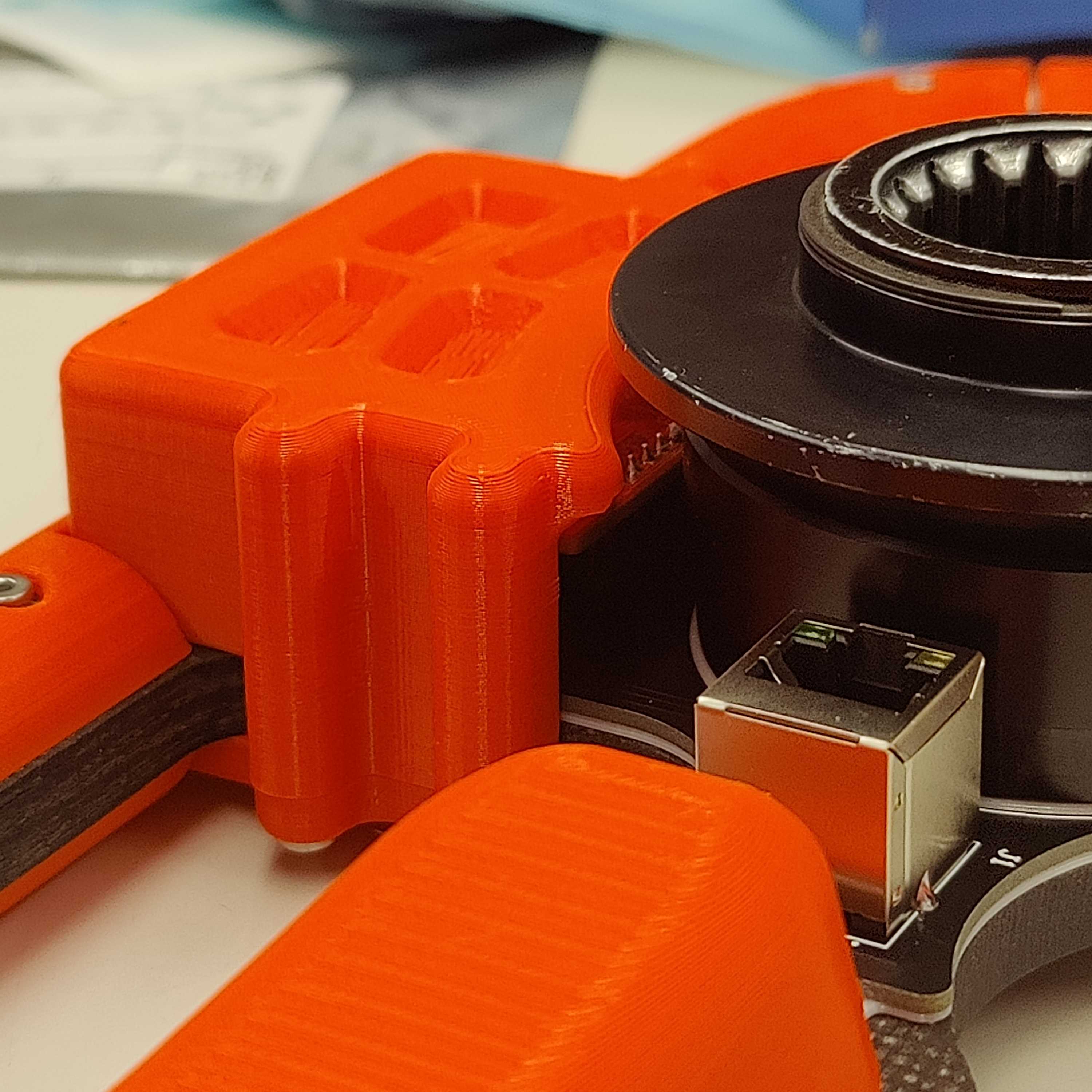
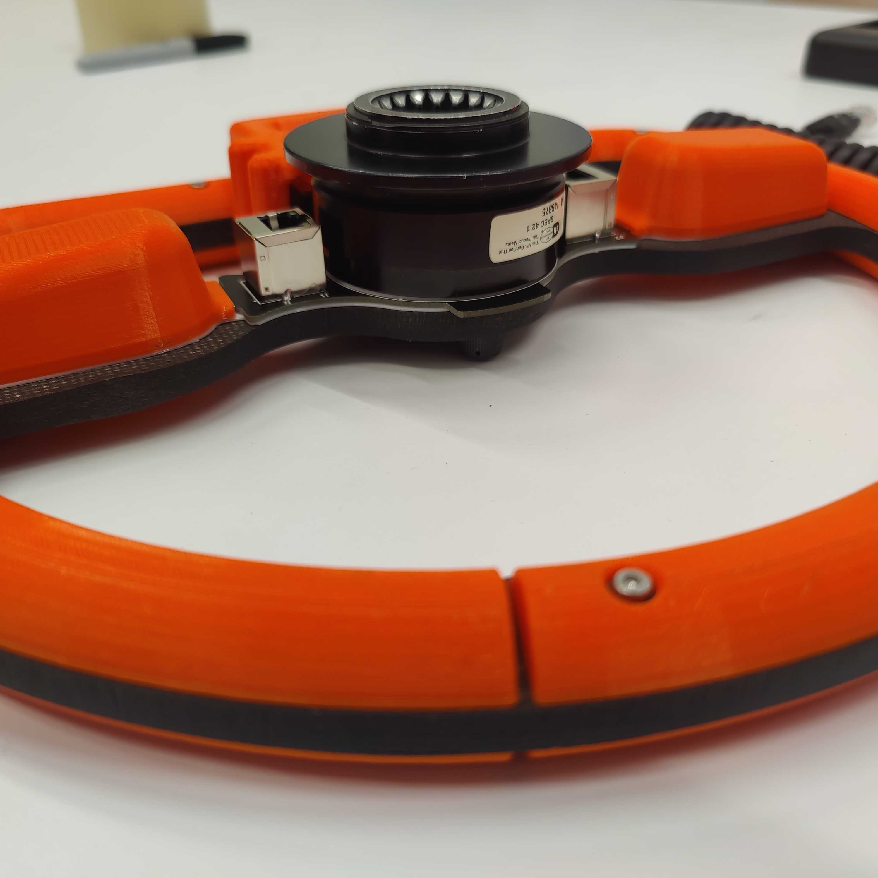
And with that the project was more or less complete. The software team was able to make a few adjustments to their code and it was connected to the car and ready to go in no time.
Over the course of the past few weeks the steering wheel has been working great while driving and has presented no issues so far and seems to have solved the ones of the previous design.
I really enjoyed making this project as allowed me to learn a lot more about the solar car club and meet more people on the team. I think the final product turned out really well and bears a striking resemblance to the CAD used to create it. Hopefully it will be able to stand up to the intense rigor of the 1300 mile American Solar Challenge this summer!
Caden Kraft Newsletter
Join the newsletter to receive the latest updates in your inbox.

