
Ironless Axial Flux Motor

After my first custom brushless motor I felt confident enough with the basic theory of how they work to make a second design with significantly more thought and math defining the design.


As my first design was made by looking at images online and implementing dimensions based on what looked right I found that there were some serious inefficiencies that could be remedied with a bit of math.
Why Axial Flux?
One of the main reasons that I chose to use an axial flux motor design was because the air gap between the magnets and the coils is more or less two dimensional. As opposed to a traditional radial flux motor this allows me to adjust the air gap with shims instead of redesigning the rotor every time to adjust it.

Another benefit to this design is that because this is a DIY project I do not have the budget to order the custom magnets with a bend for a radial flux rotor.
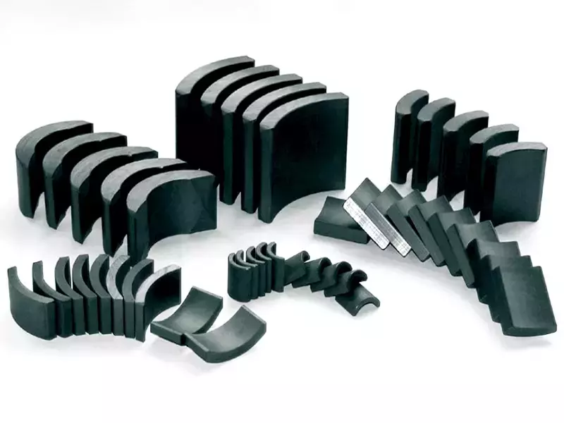
The flat nature of an axial flux motor allows me to use traditional rectangular bar magnets that can be found cheaply online in large quantities without the need to have them custom made.
Coreless Design and Halbach Array
Similarly to the magnets, due to cost constraints for this project and the manufacturing capability that I currently have in my college apartment, I am not able to custom make ferrite or steel laminate ferrous cores inside the coils.
As a ferrous core is extremely important in shaping the magnetic field around the coils, I had to research a different solution to remedy this and came across the Halbach magnet array. This works by alternating the magnet poles by 90 degrees at a time instead of 180 degrees like normal designs.
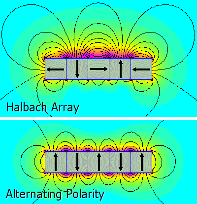
This uses extra magnets to shape the magnetic field as a iron core traditionally would. As there are very little designs on the internet that I could find the utilize a Halbach pattern I chose to implement it into my design to hopefully contribute some experience implementing it into a motor once the design is completed.
This means that while the rotor of my motor has 12 poles it actually utilizes 24 magnets to implement the Halbach design.
Defining Specifications
Next I had to define a few specifications around various aspects of the motor needed to calculate the number of coil turns needed for the final design.
I found an excellent research paper online that outlined the mathematical parameters needed to successfully create a Halbach axial flux design.


Design and Test of an Ironless Axial Flux Permanent Magnet Machine using Halbach Array
Through this paper and some preliminary CAD design as well as a quick inventory of all of the motor controllers and bearings that I had already, I was able to define certain parameters needed to calculate the coil turns below. The coil area was calculated by taking the approximate area enveloped by the outer perimeter of copper of a single coil.
| Parameter | Value |
|---|---|
| DC Bus Voltage | 24 V |
| Base Speed | 700 rpm |
| Rated Current | 7 A (rms) |
| Wire Diameter | 0.65 mm |
| Poles ($p$) | 12 |
| Coils ($c$) | 18 |
| Connection | Star (Y connection) |
| Coil Area ($A_{coil}$) | 4.92*10-4 m2 |
| Rotor Area ($A_{rotor}$) | 9.42*10-3 m2 |
| Outer Radius ($r_o$) | 65 mm |
| Inner Radius ($r_i$) | 35 mm |
| Magnetic Flux Density ($B$) | 0.5 Tesla |
I chose for the motor to have 12 poles and 18 coils as it has an efficient high winding factor.

Calculating Parameters
The first step in defining the coil turns needed is calculating the area of the motor that is covered by the magnets on the rotor.
$$\small{A_{\text{rotor}} = (p \cdot 2) \cdot (0.036 m \cdot 0.006 m)}$$
Next, I needed to define an optimal outer to inner radius ratio in order to maximize the efficiency of the motor. As the paper above says, an optimal ratio for this is around 0.5. This allowed me to define the inner and outer radius based on the 36mm*6mm*6mm magnets that I found online.
$$\small{\alpha=\frac{r_i}{r_o}}$$
Then I had to calculate the peak flux density using the equation below as well as the recommended mean air gap flux density of 0.5 Tesla from the paper above.
$$\small{\tau=\frac{F}{A_{rotor}}=\frac{Bli}{lw}=\frac{Bi}{w}=BZ}$$
$$\small{B=\frac{2B_m}{\pi}}$$
After using these two equations I arrived at a mean air gap flux density of 0.785 Tesla. Using the next couple equations I was able to use this value combined with others above to figure out the final number of coil turns.
$$\small{e_{ph}=N_{ph}A_{coil}\frac{dB(\theta)}{dt}}$$
$$\small{B(\theta)=B_m\sin{{(\omega}_et)}}$$
$$\small{e_{ph}=N_{ph}A_{coil}\omega_eB_m\cos{(\omega_et)}}$$
$$\small{N_{ph}=\frac{e_{ph}}{A_{coil}\omega_eB_m}}$$
The electrical frequency of the stator voltage can be determined using the shaft speed and number of pole pairs.
$$\small{{\omega_e}=\frac{700\ rpm}{60\ s}\cdot2\pi\cdot6}$$
Plugging in the final numbers into the equation below equates to about ~87 coils per phase of the motor.
$$\small{N_{ph}=\frac{\frac{24\ V}{\sqrt3}}{4.92\cdot{10}^{-4}\cdot\frac{700\ rpm}{60\ s}{2\pi}\cdot{6}\cdot{0.785\ T}}}$$
$$\small{N_{ph}=81.57}$$
Dividing this by six as there are 6 coils per phase it equates to around 14 turns per coil.
Finalizing the Design
Now that I had the parameters defined I started work on creating the final design. The final design will consist of mostly 3D printed parts and a 62mm*40mm*12mm unsealed roller bearing. This bearing has significantly more rigidity than the 608 skateboard bearing I used in my first design.
Here are a few renders of the final motor design that I decided on. The white/clear parts are printed in PLA while the base stator is made of PETG for the extra temperature resistance as the coils heat up.


Below is a draggable render where you can see the final explosion view of the design from multiple angles.
Here is an image of all of the different printed parts and hardware (aside from magnets and enamel wire) needed to assemble the motor.

These photos show a more in depth look at the design that I used in order to secure the bearing to the plastic piece. This has proved to work significantly better than the friction fit bearing mount seen in my first design.


Pictures of the parts I used to secure the bearing to the rotor and the stator
Finally here is an image of the final design assembled (again without magnets or coils) with a Sharpie for scale.

Last but not least, I thought I would throw in an image showing the amount of prototype parts it took to get the fitment of everything just perfect.

Assembly
Now that the printed parts are completed and they are successfully test fit I ordered the necessary magnets and wire needed to complete the motor and finally get it up and running.
The step-by-step plans for what the assembly will include are listed as below.
- Wind all 18 coils coils (0.65mm Enamel Wire)
- Measure coil resistance with University LCR meter
- Solder power leads and connectors to coils
- Assemble magnets into rotor (36x6x6mm Neodymium magnets)
- Create test stand to power and characterize properties of the motor
Here are the photos of the wound coils for the motor as well as the magnets in the rotor. I used a magnetometer app to find the northern pole of the magnets in order to properly construct the Halbach array.


Magnets in rotor (left), Would coils (right)
In order to make sure that I wound the coils correctly and the solder joints didn't induce any added resistance I took the stator assembly to one of the university LCR meters to measure resistance and inductance.


Labeled coils (left), LCR meter setup (right)
Below is a table summarizing the LCR measurements.
| AB | AC | BC | |
|---|---|---|---|
| Resistance (mOhms) | 699 | 705 | 708 |
| Inductance (uH) | 56.45 | 57.69 | 57.19 |
While coil A differed slightly I deemed this within my allotted margin of error and moved forward.
Finally once it was fully assembled I was able to hook everything up and hope that it would spin. Below is a video of its first spin.
Video of me spinning up the motor for the first time.
I would have liked to test the torque of the motor with a dynamometer but I did not have access to one at the time. Maybe I will save this for a future project but for now I'll have to leave this one here.
Conclusion
I really enjoyed this project because it was the first project I've done that required me to do a lot of research and get a baseline understanding of what was needed to complete the project before even starting.
This took quite a long time to make but I think it was ultimately worth it as I have vastly expanded my knowledge of motors and motor design and I actually was able to create a working motor. Hopefully I am able to carry the skills that I learned through this project onward to future ones.
Thanks for reading this post. If you are interested in any of my other posts they are linked below!
References
[1] T. Batzel, A. Skraba, and R. D. Massi, “Design and Test of an Ironless Axial
Flux Permanent Magnet Machine using Halbach Array,” IAJC-ISAM Joint
International Conference, vol. 88, 2014.
Caden Kraft Newsletter
Join the newsletter to receive the latest updates in your inbox.


