
Creating a 3D Printed Brushless Motor

With my work in the Iowa State Solar Car club I have learned so many things about so many different technologies that I have not had the chance of working with before.
One of the things that has come to interest me the most are motors. Getting the chance to learn and tune the motors on our car has led me to develop a further interest in how they work.
On our current car we use BLDC motors from Mitsuba in Japan directly driving our wheels inside the rims of our wheels.

With this urge to dive deeper and figure out how exactly brushless motors work I decided to try and design my own so I can experience every hurdle and roadblock and hopefully learn something from it.
Going into the design I just wanted to try my hand at making a motor without having to learn advanced motor simulation software like Ansys MotorCAD and Ansys Maxwell. My goal was simply to make a motor that works and spins on its own.
Starting a design in Autodesk Inventor, I began by creating the main profile of the stator.

I made this design using reference images I found online while adding features optimizing the design to be 3D printed. As seen above I also added slots on either side of the coil to make routing each coil and keeping it organized significantly easier while allowing all the wires to go into the center so the design can be screwed flush.
Continuing on the design I needed to create a solution for implementing a bearing. As I wanted to keep the costs down on the project I decided to use a standard open ball 608 skateboard bearing that I had lying around.

Finally I ordered some 2mm*10mm*20mm neodymium magnets off of AliExpress. I then culminated this into a final design using all of these parts.

Now it comes time to assemble the motor. I started researching different ways of winding the coils and different parameters in terms of coil winding and wire gauge that I could use to my advantage to increase the efficiency of the motor.
I started researching the differences between Wye and Delta winding configurations.

Although a Wye configuration on paper would be better suited for this motor design because of the reduced need of current to start spinning the motor. However, I chose to use the Delta configuration as it was significantly easier to wire given the design that I had.
This link below contains a lot of interesting information if you are interested in learning more about the differences in these two types of windings.

Although I could research and try to optimize the wire guage of the coil I already had a spool of 0.5mm enameled copper wire that I did not have plans to do anything with so I decided to use that.
I chose to use this wire with 60 windings across the all 6 poles of the motor in 3 individual phases.

Now that the wiring was done I needed to test the motors functionality. I hooked the motor up to an old ESC that I had from making drones and using a servo controller to manually control the RPM of the ESC. I found that the motor worked best around 14-15 volts but did not have a lot of torque output.

One thing I did notice was that I needed to flick the motor pretty hard in order for it to start spinning. This is probably due to many inefficiencies in the motor such as lacking an iron core for the electromagnet or the higher starting amperage needed for a Wye configuration.
Future Changes
Below I am going to sum up a few key takeaways that I have learned from this project and future ways I could remedy it in the next motor design that I make. I think the biggest faults in the current design are as listed below.
- Lack of iron core in the electromagnets
- Magnets are pretty weak and could be stronger
- Spacing between the coil and magnet significantly too high
- Using Delta wiring instead of Wye
Some ways that I could remedy this are by making an axial flux motor for my next design. This would allow for an extremely thin gap between the rotor and stator and because of the coil design of an axial flux motor I could also make a separate jig for more accurately winding each individual coil instead of winding around the stator all at once.

Since making this I have also learned more about motor theory and simulating motors through applications like Ansys MotorCAD and Maxwell through work that I have done at my internship at Husco Automotive.
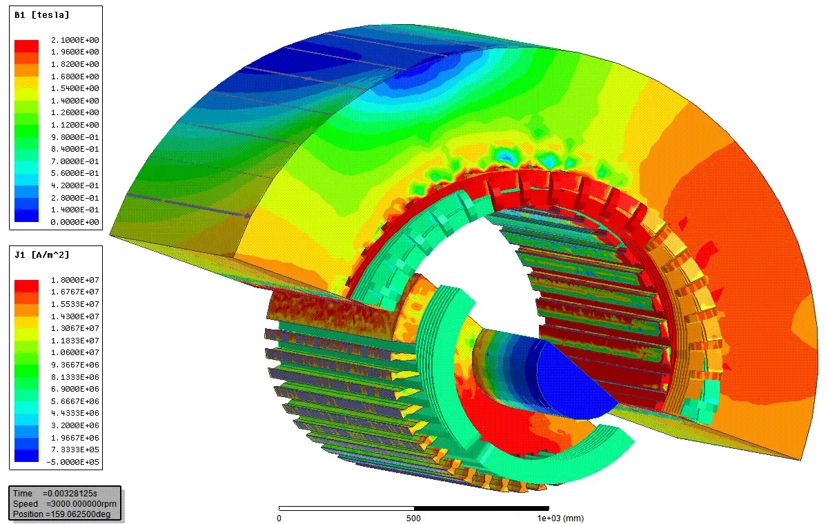

Examples of Ansys MotorCAD and Maxwell Being Used for Motor Design
Hopefully I will be able to utilize these skills in order to refine my next design to be more efficient and quantitatively thought out.
Stay tuned for that to come!
Caden Kraft Newsletter
Join the newsletter to receive the latest updates in your inbox.


