
3D Printed Dual Cycloidal Actuator

This project is a continuation of my previous axial flux motor project. If you've not yet read that I would recommend doing so.

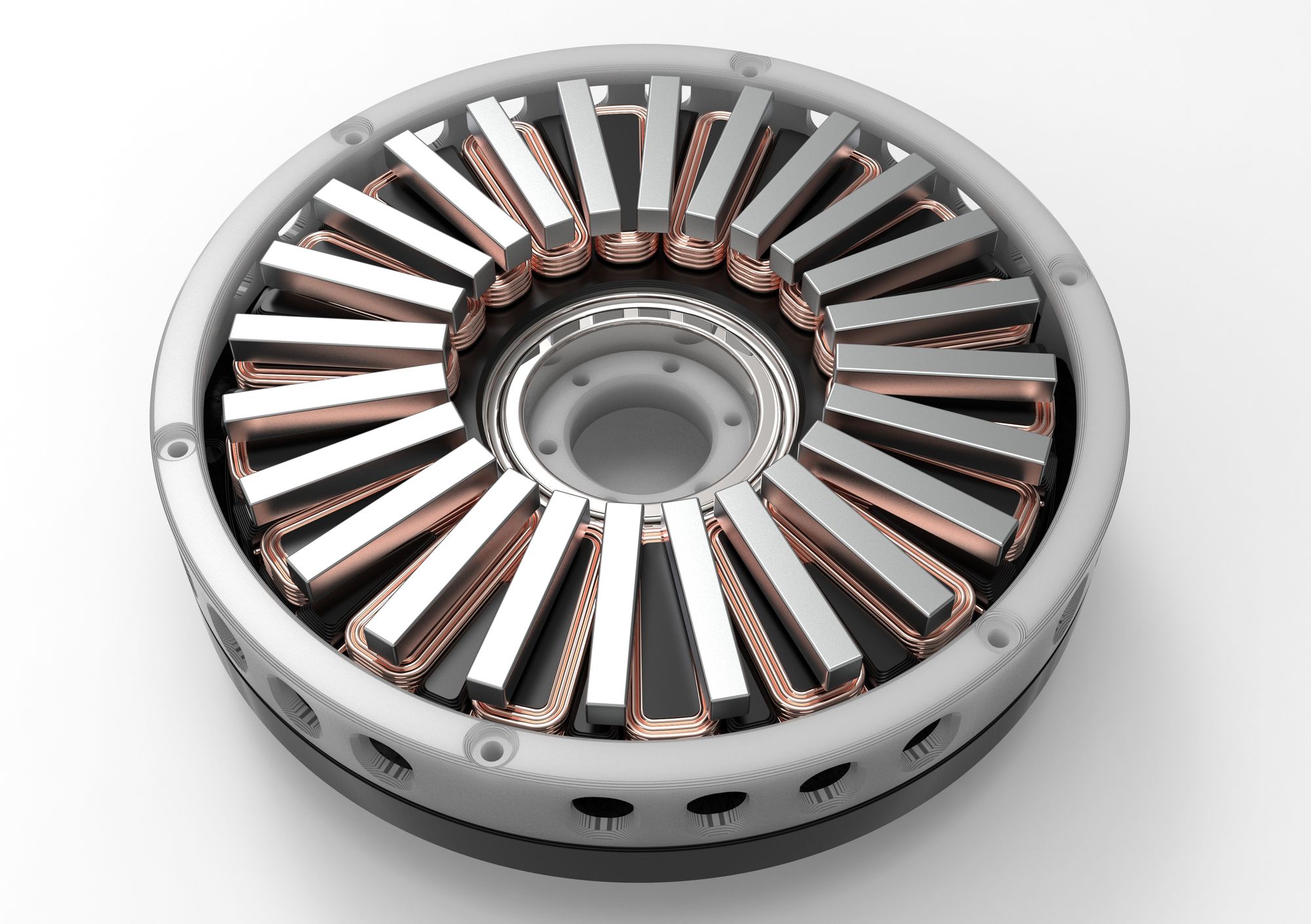
After I was finished with making my last motor project I was quite proud of the results. However, while the motor could achieve extremely high RPM's, this came at the cost of torque.
Originally I thought about rewinding the stator and possible improvements via stronger magnets and/or Iron based 3D printer filament for the stator coils among other things.
Deciding on a Gearbox
Wanting to work on something a little more different than pure motor design and not wanting to rewind any coils, I set my sights on developing a gearbox that could be integrated into my current stator design. There were 3 primary options that I was looking into when deciding what gearbox that I was going to make, Planetary, Cycloidal, and Harmonic.

Cycloidal (left), Harmonic (center), Planetary (right)
All of these options definitely seem like good ideas but I had to narrow down which one I was going to choose.
Planetary would have been the easiest and probably would have performed the best but I cut it out because I didn't really find it interesting enough and wanted to learn more about the other gearboxes.
While I admire the simplicity of the harmonic drive I was wary of my ability to manufacture the flexible parts needed. I eventually chose the cycloidal drive because it seemed like the biggest technical challenge to design as well as the fact that it looks extremely cool. Cycloidal gearboxes also have nearly no backlash which definitely made it stand out against something like a planetary gearbox with the tolerances of 3D printed parts.
Defining Project Requirements
Now that I knew what gearbox I wanted to make I started to define what I wanted the final design to look like.
- Dual cycloidal drive to reduce vibrations
- Integration of motor and gearbox into one assembly
- 70mm Z height restriction to keep a low profile
- 10:1 reduction
- Easy assembly/disassembly (no adhesives)
- Use existing stator design from axial flux motor
Actuator Design
With my requirements set, I moved on to designing the actuator. The base motor design is based on my last axial flux motor so I began modifying that in order for it to fit a gearbox. Next I had to start work on the design of the cycloidal gearbox system itself. This was quite challenging to figure out initially because the cycloid geometry is fully defined off of parametric equations.
This guide was immensely helpful in defining the geometry. After some time I had the parameters for my parametric equations ready to go based on the size and reduction that I wanted.
| Parameter | Variable | Value |
|---|---|---|
| Radius of rotor | $r$ | 67mm |
| Radius of rollers | $r_r$ | 4mm |
| Eccentricity | $e$ | 3mm |
| Number of rollers | $n$ | 10 |
$$\begin{equation}
\small{x = {r}\cos(t) - r_r\cos(t + \psi) - {e}\cos(nt)}
\end{equation}$$
$$\begin{equation}
\small{y = -{r}\sin(t) + r_r\sin(t + \psi) + {e}\sin(nt)}
\end{equation}$$
$$\begin{equation}
\small{\psi = \arctan\left(\frac{\sin((1-n)t)}{\left(\frac{r}{e}\right) - \cos((1-n)t)}\right)}
\end{equation}$$
I made an interactive graph on Desmos where you can visualize different cycloid designs quicker than you can in SOLIDWORKS.
By plotting these parametric equations from $(0 < t < \pi)$ and mirroring the result I ended up with the final geometry needed for my cycloids.

As this design uses two cycloids they actually rotate in the same direction but have inverted eccentricity with the benefit being that a lot of the vibration is canceled out as the center of mass is roughly centered instead of spinning around. This does come at the expense of added complexity.

Now it was time to finally integrate everything together into one cohesive design. One challenge I faced during this process was the admittedly arbitrary height limit that I gave myself.
There were a lot of design revisions in order to get all of the parts to fit in the allotted space. Below is an image showing a cross section of the final design with the plastic 3D printed components highlighted.

As you can see above there are some very tight gaps between a lot of the moving parts inside the gearbox as a result of needing to fit in this Z constraint. Below is an image that should give a better idea of how the motor and gearbox were integrated into a single assembly.

Once I was done combining the gearbox and motor I landed on this final design
Final Design Renders


Manufacturing and Assembly
When it came to actually manufacturing the design I had to go through quite a few prototype parts before I landed on the final geometry. There was a lot of friction problems with so many parts tightly packed together moving at high speeds so a lot of incremental improvements had to be made. Below is a picture of all the failed parts that didn't make it into the project.

However, when I finally did figure out all the issues I was able to assemble and test the actuator. Here are some photos of what the final design looks like assembled.


Different views of the actuator
Testing
Unfortunately I don't currently have access to a dynamometer to do a proper torque test. If I am able to access one I will update this post in the future with the results. Below is a video of me running the actuator on my bench.
I also took a video with the top components removed so you are able to see the cycloids in action.
My general impressions of it are fairly positive as when it's drawing around ~60W I am unable to stop the output with my hand like I easily could on the previous motor. This combined with the cycloidal nature of the gearbox I cannot feel any backlash whatsoever.
Conclusion
I really enjoyed working on this project as it is a culmination of many of the projects I've posted here over the past few years. Being able to take some wire, magnets, and plastic and assemble them in such a way where they generate rotation with enough torque that even I can't easily stop it is a pretty cool feeling and I am pretty proud of how it turned out.
One area that could be improved is the base torque of the motor. Even just reprinting the stator in Iron PLA would yield a higher torque with zero change to the design.
The other area that this actuator suffers in is friction. With the two cycloids spinning around inside the casing there is more rubbing and friction than I initially intended and I think this could be fixed by either only using a single cycloid or making the actuator taller.
I also wish I was able to do more empirical testing on the motor so I could properly characterize its performance but that may have to be a project for another day.
If you enjoyed this project check out some of my other projects that I have completed below!
Caden Kraft Newsletter
Join the newsletter to receive the latest updates in your inbox.


